
Zhe Wang, Wangkai Jiang, Kaichen Xu, Xiaoqiao Wang. Progress in Stretchable Fiber-Based Thermoelectric Materials and Devices[J]. Laser & Optoelectronics Progress, 2023, 60(13): 1316010
- Laser & Optoelectronics Progress
- Vol. 60, Issue 13, 1316010 (2023)
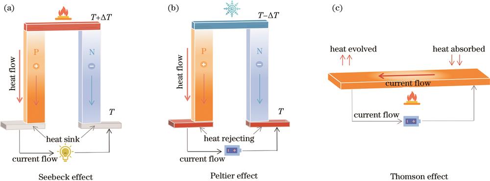
Fig. 1. Thermoelectric effect. (a) Seebeck effect for power generation; (b) Peltier effect for refrigeration; (c) Thomson effect for cooling or heating
![Preparation method of stretchable thermoelectric fibers. (a) Schematic of the chemical structure of PEDOT∶PSS and WPU, as well as the wet spinning device for producing PEDOT∶PSS/WPU composite fiber[69]; (b)(c) optical micrographs of PEDOT: PSS/WPU composite fiber in relaxed and stretched states[69]; (d) schematic of an experimental device for manufacturing CNT composite TE fiber[70]; (e) schematic of the preparation process of stretchable thermoelectric fiber yarn[71]; (f) stress-strain curves of thermoelectric fibers and pure PU fiber[71]; (g) resistance change of thermoelectric fibers under different strains[71]](/richHtml/lop/2023/60/13/1316010/img_02.jpg)
Fig. 2. Preparation method of stretchable thermoelectric fibers. (a) Schematic of the chemical structure of PEDOT∶PSS and WPU, as well as the wet spinning device for producing PEDOT∶PSS/WPU composite fiber[69]; (b)(c) optical micrographs of PEDOT: PSS/WPU composite fiber in relaxed and stretched states[69]; (d) schematic of an experimental device for manufacturing CNT composite TE fiber[70]; (e) schematic of the preparation process of stretchable thermoelectric fiber yarn[71]; (f) stress-strain curves of thermoelectric fibers and pure PU fiber[71]; (g) resistance change of thermoelectric fibers under different strains[71]
Fig. 3. Preparation method of stretchable TE fibers. (a) Schematic of continuous alternating extrusion process[73]; (b) schematic of automatic extrusion section assembly line[73]; (c) Seebeck coefficient and conductivity of thermoelectric fibers with different PEI contents[73]; (d) schematic of the fabrication of TE fibers[74]
Fig. 4. Structural design of stretchable thermoelectric spiral fibers. (a) Schematic of hydrogels with different macromolecular conformations[75]; (b) process of Janus fibers continuously prepared by parallel dual channel spinning, and spiral fibers prepared by strain programming[75]; (c) formation of helical Janus fiber in response to 900% prestrain[75]; (d) spiral fibers formed under prestrain of 400% and 900%[75]; (e) relationship between diameter and number of coils of spiral fibers and prestrain[75]; (f) structural schematic of 3D thermoelectric spiral coil[76]; (g) schematic of preparing spiral thermoelectric structures based on screw templates[77]
Fig. 5. Thermoelectric woven fabric. (a)(b) Schematic of TET in 3D and 2D modes[78]; (c) relationship between the output voltage and temperature difference of the two modes[78]; (d) structural schematic of TET[79]; (e) images of twisting, knotting, bending, and stretching TETs[79]; (f) schematic of energy collection and heat conduction in woven fabrics[80]; (g) schematic of structural changes during fabric stretching [80]
Fig. 6. Application of stretchable thermoelectric fibers in self-powered sensors. (a) Voltage signal of fibers under periodic heating[69]; (b) voltage signal of stretched fibers under different temperature differences[69]; (c)(d) voltage signal of fibers under finger touch and non-contact cold source stimulation conditions under repeated stretching [69]; (e) intelligent gloves based on thermoelectric fibers[71]; (f) thermal response time of the output voltage and voltage signal of smart gloves when they come into contact with hot and cold water respectively[71]; (g) change in resistance of fibers under different strains[83]; (h) change of fiber current at~10% strain[83]; (i) change of fiber open circuit voltage under different temperature differences and strains[83]
Fig. 7. TEG for thermal energy harvesting. (a) Photo of Janus hydrogel spring composed of >100 TE coils connected in series[75]; (b) photo of wearable TE bracelets[75]; (c) voltage and current of TE bracelets and coils[75]; (d) infrared image of TE coil wrapped around hot water pipes[75]; (e) cross section infrared and optical images of the TE device[69]; (f) open circuit voltage change before and after placement of the TE device on the forearm[69]; (g) TEG pictures[78]; (h) output voltage of TEG (15 units)[78]
Fig. 8. Cooling TET. (a)(b) Schematic of the cooling device TET for thermal regulation of the human body[79]; (c) cooling effect of TET over time[79]
|
Table 1. Common TE materials and properties
|
Table 2. Materials and properties of stretchable fiber-based thermoelectric devices


Set citation alerts for the article
Please enter your email address

© Copyright 2018-2021 | Chinese Laser Press. All Rights Reserved 沪ICP备15018463号-20