• Acta Optica Sinica (Online)
  • Vol. 1, Issue 2, 0204001 (2024)
Jianping Chen1,4, Tao Liu2, B. M. A. Rahman3, and Liang Hu1,4,*
Author Affiliations
  • 1State Key Laboratory of Advanced Optical Communication Systems and Networks, Shanghai Jiao Tong University, Shanghai 200240, China
  • 2National Time Service Center (NTSC), Chinese Academy of Sciences, Lintong710600, Shaanxi , China
  • 3Department of Electrical and Electronic Engineering, City, University of London, London EC 1 V 0HB, United Kingdom
  • 4SJTU-Pinghu Institute of Intelligent Optoelectronics, Pinghu314200, Zhejiang , China
  • show less
    DOI: 10.3788/AOSOL240449 Cite this Article Set citation alerts
    Jianping Chen, Tao Liu, B. M. A. Rahman, Liang Hu. High-Precision Fiber-Optic Time and Frequency Transfer and Device Integration (Invited)[J]. Acta Optica Sinica (Online), 2024, 1(2): 0204001 Copy Citation Text show less
    Schematic of fiber-optic based time and frequency transfer system
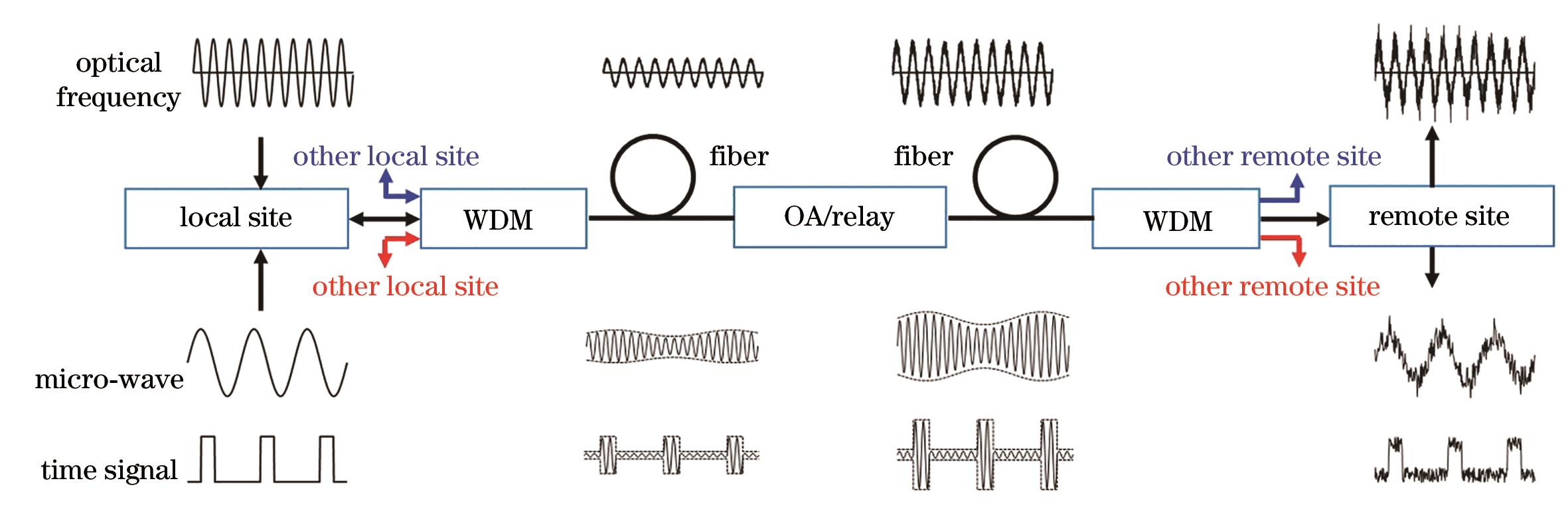
    Fig. 1. Schematic of fiber-optic based time and frequency transfer system
    Diagram of optical frequency transfer system based on passive optical phase noise cancellation
    Fig. 2. Diagram of optical frequency transfer system based on passive optical phase noise cancellation
    Performance comparison of two noise cancellation schemes
    Fig. 3. Performance comparison of two noise cancellation schemes
    Effective and group refractivity vs silicon waveguide dimensions. (a) Structure of conventional waveguide; (b) structure of polarization-insensitive waveguide; (c) neff vs w for conventional waveguide; (d) neff vs w for polarization-insensitive waveguide; (e) ng vs w for polarization-insensitive waveguide
    Fig. 4. Effective and group refractivity vs silicon waveguide dimensions. (a) Structure of conventional waveguide; (b) structure of polarization-insensitive waveguide; (c) neff vs w for conventional waveguide; (d) neff vs w for polarization-insensitive waveguide; (e) ng vs w for polarization-insensitive waveguide
    Silicon-based transceiver chip and its transmission performance. (a) Chip structure and SEM image; (b) comparison of tested transmission performance
    Fig. 5. Silicon-based transceiver chip and its transmission performance. (a) Chip structure and SEM image; (b) comparison of tested transmission performance
    PLC-based 1×16 splitter and demonstration of distributed free space optical frequency transfer. (a) Diagram of 1×16 splitter; (b) experimental setup for distributed free space optical frequency transfer; (c) tested results
    Fig. 6. PLC-based 1×16 splitter and demonstration of distributed free space optical frequency transfer. (a) Diagram of 1×16 splitter; (b) experimental setup for distributed free space optical frequency transfer; (c) tested results
    On-chip bidirectional frequency shifter based on LNOI platform and corresponding tested performance. (a) Chip structure diagram; (b) (c) chip SEM images; (d) packaged chip structure; (e) tested performance
    Fig. 7. On-chip bidirectional frequency shifter based on LNOI platform and corresponding tested performance. (a) Chip structure diagram; (b) (c) chip SEM images; (d) packaged chip structure; (e) tested performance
    InstitutionYearSchemeFiber length /kmTime deviation /psUncertainty /psFiber type
    JPL, USA552007Direct transfer20/5000A
    SP, SWE562008Unidirectional56016.4@10000 s1000B
    CESNET, CZE572010Bidirectional7448.7@500 s30@1 dB
    PTB, GER582012SS coding7340@1 d74B
    UAGH, POL592012Active compensation6015@100 s13B
    LPL, FRA602013SS coding54030@1 d250B
    SIOM, CAS, CHN612015Tree-like branching251.8@100 s80A
    SJTU, CHN622016Bidirectional TDM600061@100000 s70A
    THU, CHN262017Star-shaped2550@1 s100A
    BUPT, CHN632021Bidirectional PM155656@1000 s/A
    SJTU, CHN642021Bidirectional TDM1313432@10 s89.6A
    NTSC, CAS, CHN652024Bidirectional WDM18393.9@1000 s25.3B
    Table 1. Research progress of fiber-optic time transfer
    InstitutionYearCompensation schemeFiber length /kmFF instabilityFiber type
    UP13, FRA662008Fiber delay line862×10-18@1 dB
    NICT, JPN342009VCO compensation251×10-17@1 dB
    NMIJ, JPN292010Bidirectional OA1202.6×10-16@1 dB
    AGH, POL672011Electric delay line602×10-17@1 dB
    THU, CHN682012Multiple-access835×10-18@1 dB
    NUST, CHN692014Passive compensation1002×10-17@100000 sA
    SJTU, CHN702018VCO compensation1604.1×10-17@10000 sA
    NTSC, CAS, CHN712021Cascaded3006.8×10-18@10000 sB
    BUPT, CHN722023Multi-nodes20003.8×10-14@1 sA
    SJTU, CHN732023Balanced dual-heterodyne1503.5×10-17@10000 sA
    Table 2. Research progress of fiber-optic microwave frequency transfer
    InstitutionYearCompensation schemeFiber length /kmFF instabilityFiber type
    NIST, UAS741994Active compensation0.025/A
    NIST, USA752007Active compensation2516×10-19@100 sB
    UP13, FRA762010Laser relay3005×10-20@20 hB
    MPQ&PTB, GER162012Active compensation9204×10-19@2000 sB
    UP13, FRA772012Laser relay5403×10-19/30000 sB
    Soton, UK782015Optical injection locking2921×10-19@3200 sB
    ECNU, CHN192015Laser relay824×10-19@10000 sB
    NTSC, CAS, CHN792016Active compensation1124×10-20@10000 sB
    SJTU, CHN372020Passive compensation1452×10-19@10000 sA
    NTT, JPN472020PLC chip2401×10-18@2600 sB
    SJTU, CHN802021Silicon chip623×10-19@10000 sB
    NTSC, CAS, CHN812023EDFA relay2248.4×10-19@10000 sB
    NTSC, CAS, CHN822024Laser relay9721.1×10-19@10000 sB
    Table 3. Research progress of fiber-optic optical frequency transfer
    Jianping Chen, Tao Liu, B. M. A. Rahman, Liang Hu. High-Precision Fiber-Optic Time and Frequency Transfer and Device Integration (Invited)[J]. Acta Optica Sinica (Online), 2024, 1(2): 0204001
    Download Citation