• Study On Optical Communications
  • Vol. 49, Issue 4, 42 (2023)
Qing-rui CHEN1, Yan-long LI1, Wei-chao Lü2, Guang-bin SONG1, and jing XU1,*
Author Affiliations
  • 1Optical Communications Laboratory, Ocean College, Zhejiang University, Zhoushan 316021, China
  • 2AVIC JONHON Optronic Technology Co., Ltd., Luoyang 471000, China
  • show less
    DOI: 10.13756/j.gtxyj.2023.04.008 Cite this Article
    Qing-rui CHEN, Yan-long LI, Wei-chao Lü, Guang-bin SONG, jing XU. General Testing Methods for Underwater Wireless Optical Communication Systems[J]. Study On Optical Communications, 2023, 49(4): 42 Copy Citation Text show less
    The diagram of UWOC test system block
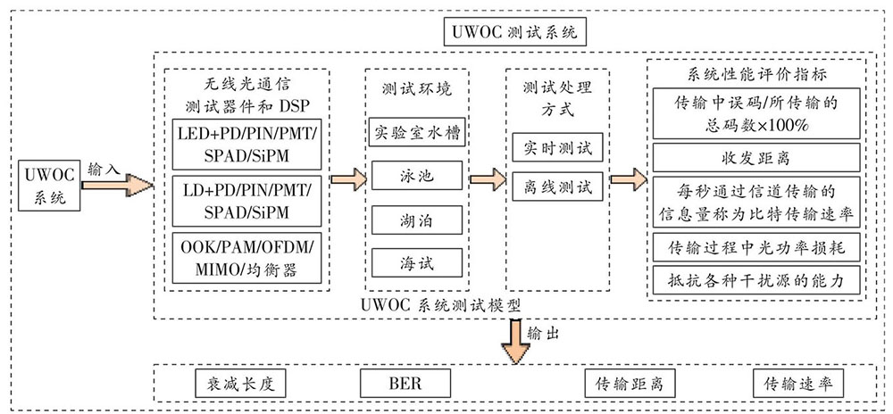
    Fig. 1. The diagram of UWOC test system block
    200 m/500 Mbit/s UWOC system setup schematic diagram[12]
    Fig. 2. 200 m/500 Mbit/s UWOC system setup schematic diagram[12]
    Zhejiang university ocean college wave-current movable bed silty harbor pool
    Fig. 3. Zhejiang university ocean college wave-current movable bed silty harbor pool
    Zhejiang university ocean college large cross-section wave-current water tank
    Fig. 4. Zhejiang university ocean college large cross-section wave-current water tank
    Zhejiang university ocean college anechoic water tank
    Fig. 5. Zhejiang university ocean college anechoic water tank
    Depth-related attenuation coefficients for different wavelengths at 12 m water depth and 1 nautical mile from the coast[49]
    Fig. 6. Depth-related attenuation coefficients for different wavelengths at 12 m water depth and 1 nautical mile from the coast[49]
    Sea trial diagram of UWOC system based on Nd∶YAG laser[49]
    Fig. 7. Sea trial diagram of UWOC system based on Nd∶YAG laser[49]
    Tri-color LD WDM-UWOC system setup schematic diagram[58]
    Fig. 8. Tri-color LD WDM-UWOC system setup schematic diagram[58]
    MOPA-based UWOC system and principle[59]
    Fig. 9. MOPA-based UWOC system and principle[59]
    UWOC experimental setup diagram based on FPGA and optical fiber combiner[60]
    Fig. 10. UWOC experimental setup diagram based on FPGA and optical fiber combiner[60]
    Single-mode pigtail green LD UWOC system setup diagram[61]
    Fig. 11. Single-mode pigtail green LD UWOC system setup diagram[61]
    Schematic diagram of NLOS UWOC system experimental setup based on ultraviolet laser[62]
    Fig. 12. Schematic diagram of NLOS UWOC system experimental setup based on ultraviolet laser[62]
    CORK optical telemetry system sea trial schematic diagram[62]
    Fig. 13. CORK optical telemetry system sea trial schematic diagram[62]
    参数LEDLD
    最小发散角/°0.500.01
    调制带宽/MHz~100>200
    温敏
    相干性不相干相干
    安全性
    Table 1. Comparison of LED and LD parameters
    年份速率距离/m光源探测器文献
    2017800 Mbit/s60440 nm LEDPIN[25]
    201810 Mbit/s57470 nm LED阵列APD[26]
    201919 Mbit/s8470 nm LED阵列PMT[27]
    2019200 Mbit/s1405 nm LED阵列APD[28]
    20194.92 Gbit/s51450 nm微LED阵列PIN[20]
    202020.09 Gbit/s1LED阵列PIN[29]
    2021500 Mbit/s150450 nm LEDPMT[11]
    2022130 Mbit/s7520 nm LEDPMT[30]
    Table 2. Recent test results of UWOC systems based on LED light sources
    年份速率距离/m光源探测器文献
    201716 Gbit/s10.0488 nm LDAPD[31]
    201712.4 Gbit/s1.7450 nm LDPIN[32]
    201710.8 Mbit/s10.2520 nm LDPIN[33]
    20187.33 Gbit/s15.0450 nm LDAPD[34]
    201950 Mbit/s3.0450 nm LDPIN[35]
    201912.62 Gbit/s35.0450 nm LDPIN[36]
    20202 Mbit/s117.0450 nm LDSPAD[37]
    20221 Gbit/s100.0450 nm LDPMT[38]
    Table 3. Recent test results of UWOC systems based on LD light sources
    水体类型吸收系数/m-1散射系数/m-1衰减系数/m-1
    纯海水0.0480.0030.051
    清澈海水0.1140.0370.151
    沿海海水0.1790.2190.398
    浑浊海水0.3581.8662.183
    Table 4. Parameter comparison of different seawater[56]
    Qing-rui CHEN, Yan-long LI, Wei-chao Lü, Guang-bin SONG, jing XU. General Testing Methods for Underwater Wireless Optical Communication Systems[J]. Study On Optical Communications, 2023, 49(4): 42
    Download Citation