• Acta Optica Sinica
  • Vol. 44, Issue 18, 1822003 (2024)
Run Wang1,2 and Zhouping Su1,2,*
Author Affiliations
  • 1Jiangsu Provincial Research Center of Light Industrial Opto-electronic Engineering and Technology, School of Science, Jiangnan University, Wuxi 214122, Jiangsu , China
  • 2School of Science, Jiangnan University, Wuxi 214122, Jiangsu , China
  • show less
    DOI: 10.3788/AOS231837 Cite this Article Set citation alerts
    Run Wang, Zhouping Su. MEMS-Based Panoramic LiDAR System with Separated Transmitting and Receiving Modules[J]. Acta Optica Sinica, 2024, 44(18): 1822003 Copy Citation Text show less
    Conceptual diagram of MEMS LiDAR profile with separated transmitting and receiving
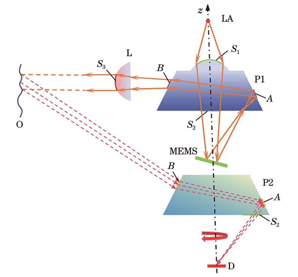
    Fig. 1. Conceptual diagram of MEMS LiDAR profile with separated transmitting and receiving
    Structure diagrams of scanning optical module. (a) yoz plane structure; (b) xoy plane structure
    Fig. 2. Structure diagrams of scanning optical module. (a) yoz plane structure; (b) xoy plane structure
    Structure diagrams of multi-field scanning module. (a) yoz plane multi-field structure; (b) xoy plane multi-field structure
    Fig. 3. Structure diagrams of multi-field scanning module. (a) yoz plane multi-field structure; (b) xoy plane multi-field structure
    Profile diagrams of multi-field luminous intensity distribution. (a) Divergence angle of each vertical field of view; (b) divergence angle of each horizontal field of view
    Fig. 4. Profile diagrams of multi-field luminous intensity distribution. (a) Divergence angle of each vertical field of view; (b) divergence angle of each horizontal field of view
    Structure diagram of yoz plane multi-field simulation
    Fig. 5. Structure diagram of yoz plane multi-field simulation
    Irradiance distribution diagrams. (a) Irradiance distribution diagrams of the target surface at different locations; (b) irradiance distribution diagram at 200 m
    Fig. 6. Irradiance distribution diagrams. (a) Irradiance distribution diagrams of the target surface at different locations; (b) irradiance distribution diagram at 200 m
    Comparison diagrams of the model divergence angle before and after adding annular lens to the scanning optical module structure. (a) Before adding annular lens; (b) after adding annular lens
    Fig. 7. Comparison diagrams of the model divergence angle before and after adding annular lens to the scanning optical module structure. (a) Before adding annular lens; (b) after adding annular lens
    Structure diagrams of receiving optical module. (a) yoz plane structure diagram; (b) xoz plane structure diagram
    Fig. 8. Structure diagrams of receiving optical module. (a) yoz plane structure diagram; (b) xoz plane structure diagram
    Received spot diagram
    Fig. 9. Received spot diagram
    TypeParameter
    MaterialPC
    Critical angle of total reflection /(°)38.942
    Angle between the total reflector and the horizontal direction /(°)60
    Radius of curvature of spherical surface S1 /mm19.93
    Radius of curvature of spherical surface S3 /mm35.88
    Tilt angle of the MEMS mirror /(°)14
    Table 1. Lens parameters for panoramic scanning MEMS LiDAR system
    ParameterValue
    P0 /W45
    D /mm21
    L /m200
    ηsys 10.932
    ηsys 20.980
    ηatm0.992
    ρ0.4
    θ /(°)0
    Table 2. Parameters of LiDAR system with separated transmitting and receiving