• Laser & Optoelectronics Progress
  • Vol. 60, Issue 16, 1615003 (2023)
Lingfei Liu, Daocheng Yuan*, and Lianxin Zhang
Author Affiliations
  • Institute of Machinery Manufacturing Technology, China Academy of Engineering Physics, Mianyang 621000, Sichuan, China
  • show less
    DOI: 10.3788/LOP222509 Cite this Article Set citation alerts
    Lingfei Liu, Daocheng Yuan, Lianxin Zhang. Binocular Vision Method for Measuring Shaft-in-Hole Assembly Parameters[J]. Laser & Optoelectronics Progress, 2023, 60(16): 1615003 Copy Citation Text show less
    Intersection line of hole plane and shaft. (a) Actual location of the intersection line; (b) relationship between the intersection line and the hole edge
    Fig. 1. Intersection line of hole plane and shaft. (a) Actual location of the intersection line; (b) relationship between the intersection line and the hole edge
    Overall schematic of the assembly system
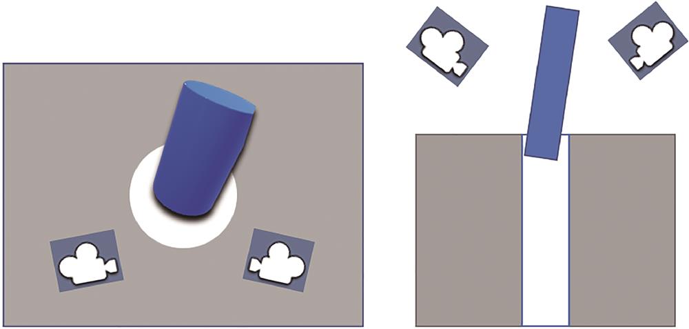
    Fig. 2. Overall schematic of the assembly system
    Coordinate relationship of the system
    Fig. 3. Coordinate relationship of the system
    Imaging projection. (a) Imaging projection process of the outermost bus of the shaft; (b) top view; (c) imaging map
    Fig. 4. Imaging projection. (a) Imaging projection process of the outermost bus of the shaft; (b) top view; (c) imaging map
    Calculation process of the center position of the shaft
    Fig. 5. Calculation process of the center position of the shaft
    Reprojection error analysis
    Fig. 6. Reprojection error analysis
    Calibration area division
    Fig. 7. Calibration area division
    Overall experimental procedure
    Fig. 8. Overall experimental procedure
    Experimental setup
    Fig. 9. Experimental setup
    Original image captured by the two cameras. (a) Image before assembly; (b) image after shaft placement
    Fig. 10. Original image captured by the two cameras. (a) Image before assembly; (b) image after shaft placement
    Recognition result. (a) Intersection line before calibration; (b) calibration diagram; (c) calibrated intersection line, which is also the final result
    Fig. 11. Recognition result. (a) Intersection line before calibration; (b) calibration diagram; (c) calibrated intersection line, which is also the final result
    Hole and shaft condition under extreme condition
    Fig. 12. Hole and shaft condition under extreme condition
    Comparison of data before and after calibration. (a) Comparison of measured values; (b) comparison of mean relative errors
    Fig. 13. Comparison of data before and after calibration. (a) Comparison of measured values; (b) comparison of mean relative errors
    Vertical shot of the experimental equipment and original image
    Fig. 14. Vertical shot of the experimental equipment and original image
    Measurement No.d /mmRelative error /%
    10.300720.28
    20.194922.04
    30.289315.72
    40.25843.36
    50.203418.64
    Table 1. Measurement results and relative error before error calibration
    Measurement No.d /mmRelative error /%
    10.26787.12
    20.22759.00
    30.26445.76
    40.25732.92
    50.23257.00
    Table 2. Measurement results and relative error after error calibration
    Measurement No.d /mmRelative error /%
    10.26706.80
    20.26325.28
    30.22898.44
    40.25763.04
    50.24342.64
    Table 3. Measurement results and relative error of extended experiment after calibration
    Lingfei Liu, Daocheng Yuan, Lianxin Zhang. Binocular Vision Method for Measuring Shaft-in-Hole Assembly Parameters[J]. Laser & Optoelectronics Progress, 2023, 60(16): 1615003
    Download Citation