
Zengyong Liu, Hongqian Cao, Fei Xu, Yanqing Lu. Graphene Nanoelectromechanical System and Its Integration with Optical Fiber[J]. Laser & Optoelectronics Progress, 2019, 56(11): 110006
- Laser & Optoelectronics Progress
- Vol. 56, Issue 11, 110006 (2019)
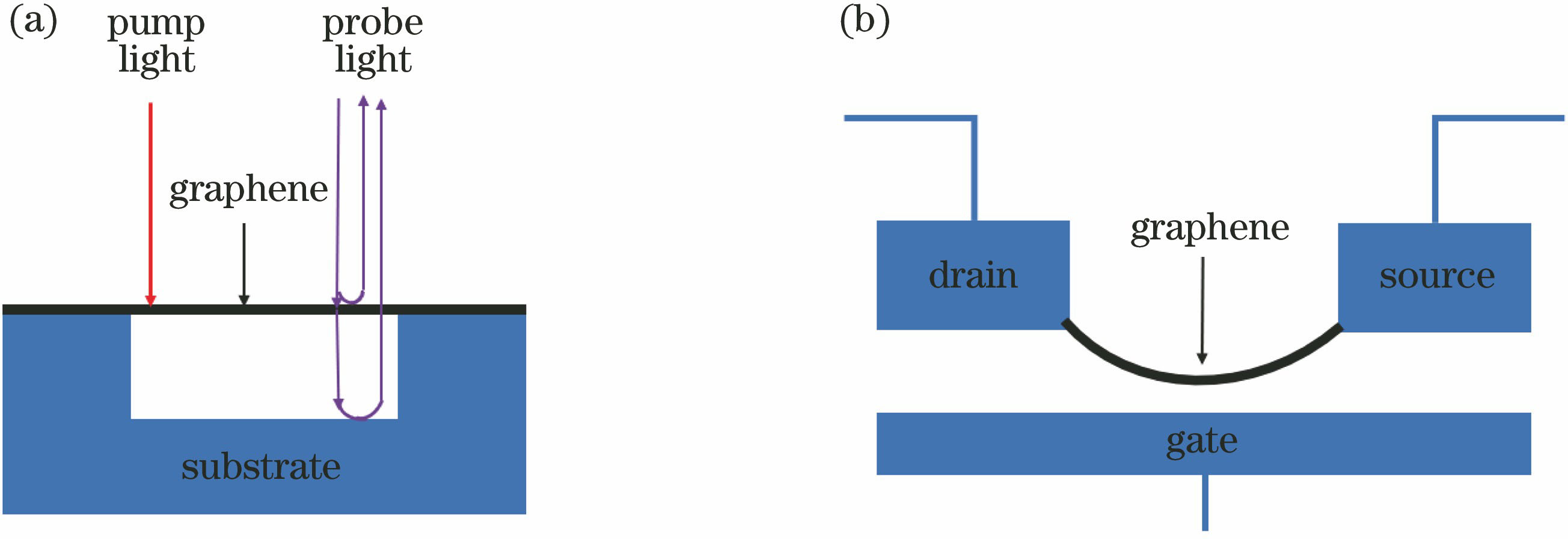
Fig. 1. Schematic of graphene nanoelectromechanical system. (a) Optical excitation and optical detection; (b) electrical excitation and electrical detection
![Resonant peak of typical graphene nanoelectromechanical system[21]](/richHtml/lop/2019/56/11/110006/img_2.jpg)
Fig. 2. Resonant peak of typical graphene nanoelectromechanical system[21]
Fig. 3. Application diagram of graphene nanoelectromechanical system. (a) Acoustic detection of graphene nanoelectromechanical system[29]; (b) thermal radiation detection of graphene nanoelectromechanical system[16]
Fig. 4. Flow chart for fabrication of graphene nanoelectromechanical system on fiber. (a) PMMA/graphene/Cu suspended on FeCl3 solution surface[12]; (b)PMMA/graphene film transferred to silica capillary end face; (c) acetone used to dissolve PMMA polymers; (d) silica capillary end face covered with graphene film only
Fig. 5. All-fiber system for excitation and testing of graphene nanoelectromechanical systems[12] (inset: F-P cavity formed by fiber end face and graphene in ceramic sleeve)
Fig. 6. Application diagram of all-fiber graphene nanoelectromechanical system. (a) Current sensor based on all-fiber graphene nanoelectromechanical system[36]; (b) resonant frequency versus I2; (c) magnetic field sensor based on all-fiber graphene nanoelectromechanical system[21]; (d) resonant frequency versus magnetic field intensity


Set citation alerts for the article
Please enter your email address

© Copyright 2018-2021 | Chinese Laser Press. All Rights Reserved 沪ICP备15018463号-20