
Cailing Fu, Zhenwei Peng, Pengfei Li, Yanjie Meng, Huajian Zhong, Chao Du, Yiping Wang. Research on Distributed Fiber Temperature/Strain/Shape Sensing Based on OFDR[J]. Laser & Optoelectronics Progress, 2023, 60(11): 1106007
- Laser & Optoelectronics Progress
- Vol. 60, Issue 11, 1106007 (2023)
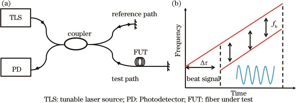
Fig. 1. Schematic diagram of frequency modulated continuous wave interferometer. (a) Michelson interferometer structure; (b) laser linear sweep light
![Rayleigh scattering of standard single-mode fibers is enhanced by UV laser exposure[17]. (a) Schematic diagram of exposure area of UV laser exposure method; (b) Gain spectrum of Rayleigh scattering enhanced single mode fiber with optimal exposure parameters](/richHtml/lop/2023/60/11/1106007/img_02.jpg)
Fig. 2. Rayleigh scattering of standard single-mode fibers is enhanced by UV laser exposure[17]. (a) Schematic diagram of exposure area of UV laser exposure method; (b) Gain spectrum of Rayleigh scattering enhanced single mode fiber with optimal exposure parameters
Fig. 3. Fabrication of weak scattering point array (WSPA) in SMF using femtosecond laser self-focusing technique[11]. (a) Schematic diagram of WSPA processing; (b) obtained Rayleigh scattering enhanced spectrum of WSPA
Fig. 4. Fabrication of weak scattering point array (WSPA) in each core of multicore fiber using femtosecond laser self-focusing technique[18]
Fig. 5. Micro-cavity arrays fabricated by femtosecond laser micro-machining technology[19]
Fig. 6. Fabrication of weak fiber Bragg grating (WFBG) array in SMF using femtosecond laser technology[22]. (a) Distance domain spectra of 200 identical WFBG; (b) enlarged view of the 89th to 92nd grating
Fig. 7. Zero crossing resampling(ZCR) method and instantaneous optical frequency domain(IOFR) method eliminate nonlinear frequency sweep of light source[30]. (a) Schematic diagram of ZCR method; (b) schematic diagram of IOFR method; (c) obtained Rayleigh scattering spectra of optical fiber under test using uncompensated method, zero-crossing resampling method and instantaneous optical frequency resampling method
Fig. 8. Flow chart of the post-processing method based on combining distance compensation and image wavelet denoising[7]
Fig. 9. Distributed high temperature sensing based on obtained weak micro-cavity array (WMCA)[19]. (a) Schematic of WMCA placed in the tube furnace; (b) measured optical frequency shift of WMCA with temperature change;(c)temperature variation in areas from 2.50 to 2.55 m
Fig. 10. Distributed strain sensing based on standard single-mode fiber and UV-exposed Rayleigh scattering enhanced fiber[17]. (a) Standard single-mode fiber strain sensing; (b)UV-exposed Rayleigh scattering enhanced fiber strain sensing
Fig. 11. Multi-core fiber 3D shape sensing technology based on vector projection[18]


Set citation alerts for the article
Please enter your email address

© Copyright 2018-2021 | Chinese Laser Press. All Rights Reserved 沪ICP备15018463号-20