
Wang Ma, Jia Qian, Siying Wang, Rui Ma, Xing Li, Shipei Dang, Xing Li, Chen Bai, Dan Dan, Baoli Yao. Recent Advances in Super-Resolution and Optical Sectioning of Digital-Micromirror Device-Based Structured-Illumination Microscopy (Invited)[J]. Laser & Optoelectronics Progress, 2024, 61(6): 0618001
- Laser & Optoelectronics Progress
- Vol. 61, Issue 6, 0618001 (2024)
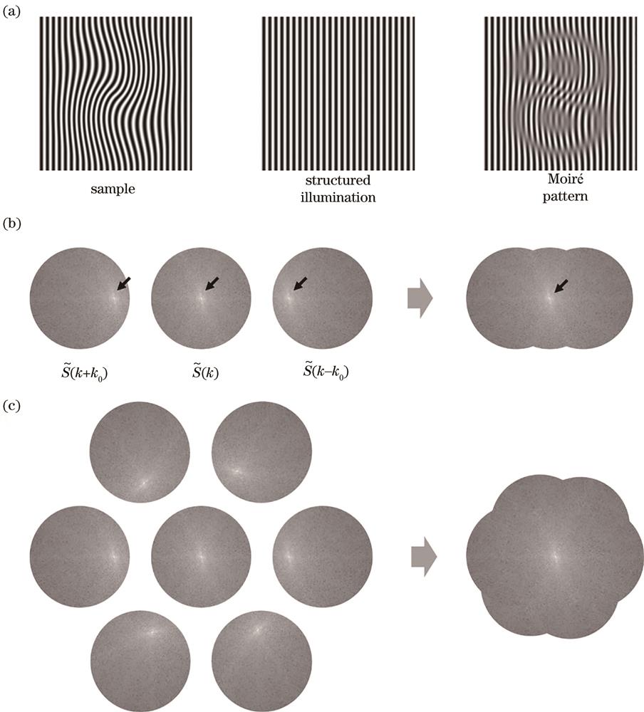
Fig. 1. The principle of spectrum expansion in SIM. (a) The overlapping of the sample and the illumination patterns produces low-frequency Moiré fringes through frequency beating; (b) the expansion and fusion of the sample spectrum under structured illumination along one single orientation; (c) the isotropic expansion and fusion of the sample spectrum under structured illumination along three orientations
![The principle and flowchart of spatial domain reconstruction of SR-SIM image[23]. (a) Schematic diagram of the PSF compression in SDR; (b) the PSF's FWHM value variation with the spatial frequency of the illumination fringes; (c) the comparison of SDR and FDR workflow](/richHtml/lop/2024/61/6/0618001/img_02.jpg)
Fig. 2. The principle and flowchart of spatial domain reconstruction of SR-SIM image[23]. (a) Schematic diagram of the PSF compression in SDR; (b) the PSF's FWHM value variation with the spatial frequency of the illumination fringes; (c) the comparison of SDR and FDR workflow
Fig. 3. Principle of the super-resolution and optical section integrated SIM[41]
Fig. 4. Principle of DMD. (a) DMD chip; (b) structure of the DMD micromirror array; (c) illustration of the incident and output light on the DMD; (d) schematic of the incident light modulation in three different states of micromirrors
Fig. 5. Schematic diagrams of generating structured illumination using DMD projection. (a) Grating projection method; (b) DMD projection method; (c) the conversion from binary periodic square patterns to sinusoidal patterns
Fig. 6. Typical optical paths for generating structured illumination based on SLM laser interferometry and DMD laser interferometry. (a) SLM[44]; (b) DMD[76]
Fig. 7. The model of DMD two-dimensional blazed diffractive gratings and the analysis of diffracted beams[98]
Fig. 8. The non-paraxial diffraction model of DMD[99]
Fig. 9. Timeline of DMD-SIM development
Fig. 10. The setup of LiDMD-SIM[102]
Fig. 11. Schematic of the hybrid multifocal structured illumination microscope[103]
Fig. 12. The dual color DMD-SIM microscope[104]
Fig. 13. The schematic of three-wavelength DMD-SIM super-resolution microscopy[105]
Fig. 14. The schematic of laser illumination speckle-free DMD-SIM super-resolution microscopy[106]
Fig. 15. Imaging results of DMD-3DSIM[76]
Fig. 16. The schematic of multi-color DMD-SIM based on grating dispersion compensation[107]
Fig. 17. Full-Color optical sectioning three-dimensional microscopy based on DMD-SIM[108]
Fig. 18. Schematic diagram of the C-SIM system[109]
Fig. 19. Imaging results of HDR-C-SIM[111]
Fig. 20. Fast optical sectioning algorithm of SIM based on Hilbert transform[113]
Fig. 21. Configuration of SIMscope3D and its imaging results[7]
Fig. 22. Imaging results of Fourier Domain-based High-Quality SIM optical sectioning reconstruction method[114]
|
Table 1. Comparison of different reconstruction algorithms for SR-SIM
|
Table 2. Comparison of DMD-SIM with other types of SIM


Set citation alerts for the article
Please enter your email address

© Copyright 2018-2021 | Chinese Laser Press. All Rights Reserved 沪ICP备15018463号-20