• Infrared and Laser Engineering
  • Vol. 52, Issue 1, 20220328 (2023)
Guangfeng Yang1, Feng Gao2, Jing Cui1,*, and Anyuan Xue3
Author Affiliations
  • 1School of Aviation Engineering, Civil Aviation University of China, Tianjin 300300, China
  • 2School of Transportation Science and Engineering, Civil Aviation University of China, Tianjin 300300, China
  • 3School of Energy and Power Engineering, University of Shanghai for Science and Technology, Shanghai 200093, China
  • show less
    DOI: 10.3788/IRLA20220328 Cite this Article
    Guangfeng Yang, Feng Gao, Jing Cui, Anyuan Xue. Effect of scanning speed on microstructure and properties of 300M steel cladding C276 coating[J]. Infrared and Laser Engineering, 2023, 52(1): 20220328 Copy Citation Text show less
    Macroface topography of the coated front and cross section. (a1)-(d1) Front shape;(a2)-(d2) Cross section shape
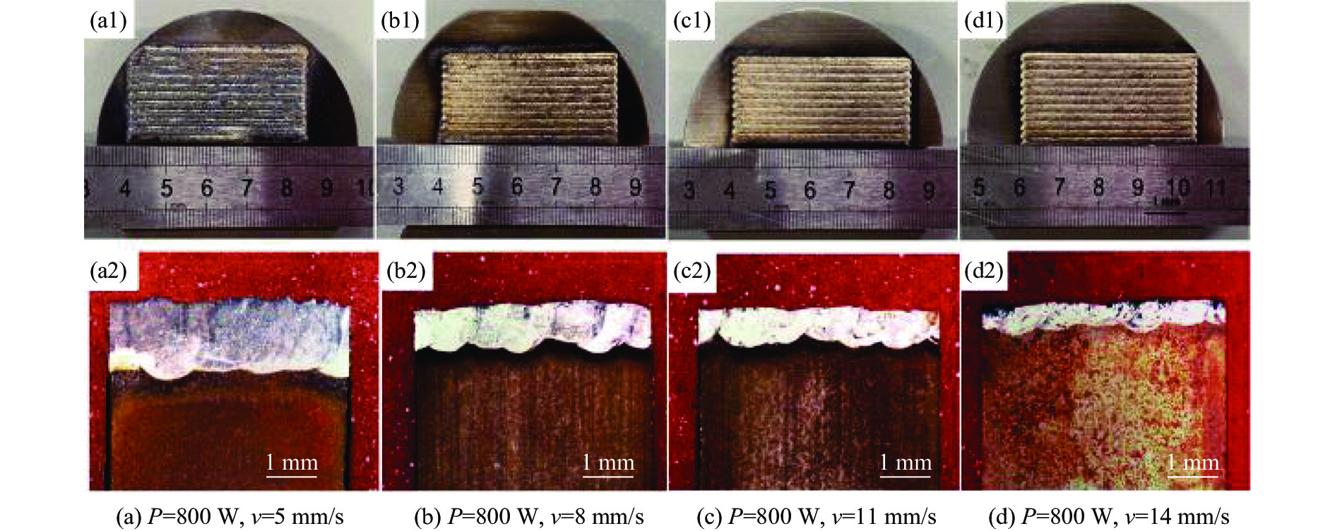
    Fig. 1. Macroface topography of the coated front and cross section. (a1)-(d1) Front shape;(a2)-(d2) Cross section shape
    XRD diffraction pattern
    Fig. 2. XRD diffraction pattern
    Grain structure distribution of laser cladding single and multi-channel forming. (a) Single channel grain structure distribution; (b) Multi-channel grain structure distribution
    Fig. 3. Grain structure distribution of laser cladding single and multi-channel forming. (a) Single channel grain structure distribution; (b) Multi-channel grain structure distribution
    Microscopic tissue topography of the central area of the C276 coating. (a1)-(d1) Coating and substrate handover zone; (a2)-(d2) Coating in the middle; (a3)-(d3) Coating top
    Fig. 4. Microscopic tissue topography of the central area of the C276 coating. (a1)-(d1) Coating and substrate handover zone; (a2)-(d2) Coating in the middle; (a3)-(d3) Coating top
    Microtissue topography of the C276 coating lap area. (a1)-(d1) Coating and substrate handover zone; (a2)-(d2) Coating in the middle; (a3)-(d3) Coating top
    Fig. 5. Microtissue topography of the C276 coating lap area. (a1)-(d1) Coating and substrate handover zone; (a2)-(d2) Coating in the middle; (a3)-(d3) Coating top
    Distribution diagram of EDS element. (a) EDS element distribution at the junction of coating and matrix; (b) Distribution of EDS elements at coating lap
    Fig. 6. Distribution diagram of EDS element. (a) EDS element distribution at the junction of coating and matrix; (b) Distribution of EDS elements at coating lap
    Microhardness of the coating center area and lap area. (a) Central zone; (b) Lapping area
    Fig. 7. Microhardness of the coating center area and lap area. (a) Central zone; (b) Lapping area
    Friction coefficient curves of 300M steel and coating
    Fig. 8. Friction coefficient curves of 300M steel and coating
    Weight loss and wear rate of 300M steel and coating test piece
    Fig. 9. Weight loss and wear rate of 300M steel and coating test piece
    300M steel and coating electrochemical curves. (a) Polarization curves; (b) Nyquist graph
    Fig. 10. 300M steel and coating electrochemical curves. (a) Polarization curves; (b) Nyquist graph
    CSiMnCrMoNiPSVFe
    0.411.660.640.710.371.900.0090.00130.008Bal.
    Table 1. Chemical composition of 300M steel (wt%)
    CSiMnCrMoWCoNi
    0.00120.850.5315.5816.224.151.87Bal.
    Table 2. Chemical composition of Hastelloy C276 (wt%)
    SpecimenIcorr/A·cm2Ecorr/V
    300M8.508 E-5−0.351
    H11.674 E-5−0.247
    H21.536 E-5−0.221
    H33.263 E-5−0.265
    H42.995 E-5−0.272
    Table 3. Polarization curve fitting results
    Guangfeng Yang, Feng Gao, Jing Cui, Anyuan Xue. Effect of scanning speed on microstructure and properties of 300M steel cladding C276 coating[J]. Infrared and Laser Engineering, 2023, 52(1): 20220328
    Download Citation