• Laser & Optoelectronics Progress
  • Vol. 60, Issue 18, 1811003 (2023)
Cheng Xu1, Xinyang Han1, Zhenyang Luo1, Tiefeng Yang1..., Depeng Kong2, Lijun Chen3, Dai Wu3, Peng Li3, Limin Xu4, Heng Wu4, Huihui Lu1, Zhe Chen5,** and Heyuan Guan1,*|Show fewer author(s)
Author Affiliations
  • 1Guangdong Provincial Key Laboratory of Optical Fiber Sensing and Communications Jinan University, Guangzhou 510632, Guangdong , China
  • 2Key Laboratory of Transient Optics and Photonics, Xi'an Institute of Optics and Precision Mechanics, Chinese Academy of Sciences, Xi'an 710119, Shaanxi , China
  • 3Institute of Applied Electronics, CAEP, Mianyang 621900, Sichuan , China
  • 4Guangdong Provincial Key Laboratory of Cyber-Physical System, Guangdong University of Technology, Guangzhou 510006, Guangdong , China
  • 5Jihua Laboratory, Foshan 528200, Guangdong , China
  • show less
    DOI: 10.3788/LOP231416 Cite this Article Set citation alerts
    Cheng Xu, Xinyang Han, Zhenyang Luo, Tiefeng Yang, Depeng Kong, Lijun Chen, Dai Wu, Peng Li, Limin Xu, Heng Wu, Huihui Lu, Zhe Chen, Heyuan Guan. Novel Optically Controlled GaAs/Side-Polished Terahertz Fiber Modulator[J]. Laser & Optoelectronics Progress, 2023, 60(18): 1811003 Copy Citation Text show less
    Schematic diagram of the structure of the microstructured terahertz fiber model
    Fig. 1. Schematic diagram of the structure of the microstructured terahertz fiber model
    Simulation results of the complete terahertz fiber. (a) Effective refractive index variation of the fundamental mode in the range of 0.1-1.2 THz; (b) mode field diagram at 0.675 THz (outer layer is perfectly matched layer and air layer)
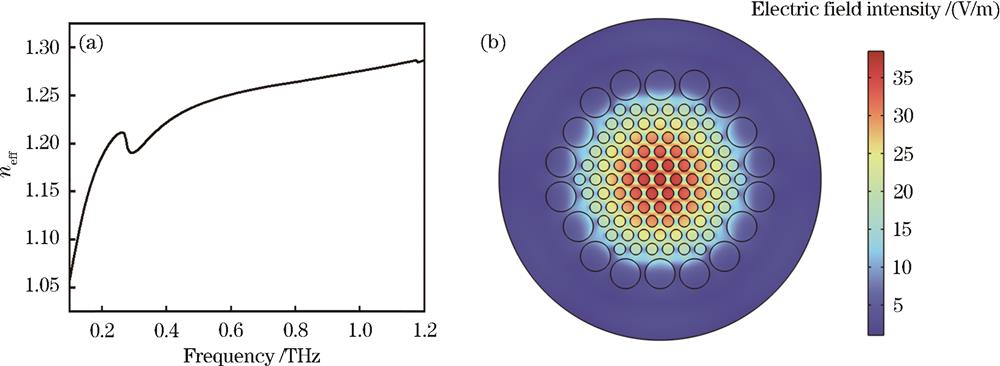
    Fig. 2. Simulation results of the complete terahertz fiber. (a) Effective refractive index variation of the fundamental mode in the range of 0.1-1.2 THz; (b) mode field diagram at 0.675 THz (outer layer is perfectly matched layer and air layer)
    Simulation results of side-polished terahertz fiber. (a) Confinement loss plots of terahertz fibers with different side throw depths; (b) mode field distribution of terahertz fibers with different side throw depths at 0.675 THz
    Fig. 3. Simulation results of side-polished terahertz fiber. (a) Confinement loss plots of terahertz fibers with different side throw depths; (b) mode field distribution of terahertz fibers with different side throw depths at 0.675 THz
    Simulation results of side-polished terahertz fiber after integrating GaAs. (a) GaAs/SPTF model schematic and mode field diagram; (b) device limiting loss under different GaAs conductivity when side-polished three-layer small air holes; (c) limiting loss difference variation under different GaAs conductivity when side-polished three-layer small air holes
    Fig. 4. Simulation results of side-polished terahertz fiber after integrating GaAs. (a) GaAs/SPTF model schematic and mode field diagram; (b) device limiting loss under different GaAs conductivity when side-polished three-layer small air holes; (c) limiting loss difference variation under different GaAs conductivity when side-polished three-layer small air holes
    Diagrams of device preparation equipment. (a) Schematic diagram of the side-polished equipment; (b) photovoltaic device integration platform
    Fig. 5. Diagrams of device preparation equipment. (a) Schematic diagram of the side-polished equipment; (b) photovoltaic device integration platform
    Modulation depth test system structure schematic
    Fig. 6. Modulation depth test system structure schematic
    Test results of side-polished fiber coated with UV adhesive under different power laser irradiation. (a) Time domain spectrum; (b) frequency domain spectrum
    Fig. 7. Test results of side-polished fiber coated with UV adhesive under different power laser irradiation. (a) Time domain spectrum; (b) frequency domain spectrum
    GaAs/SPTF test results with a remaining thickness of 1.55 mm in the side throw. (a) Time domain spectrum at different laser powers; (b) frequency domain spectrum at different laser powers; (c) modulation depth spectrum at different laser powers; (d) correspondence between modulation depth and laser power at 0.55 THz
    Fig. 8. GaAs/SPTF test results with a remaining thickness of 1.55 mm in the side throw. (a) Time domain spectrum at different laser powers; (b) frequency domain spectrum at different laser powers; (c) modulation depth spectrum at different laser powers; (d) correspondence between modulation depth and laser power at 0.55 THz
    GaAs/SPTF test results with a remaining thickness of 1.80 mm in the side throw. (a) Time domain spectrum at different laser powers; (b) frequency domain spectrum at different laser powers; (c) modulation depth spectrum at different laser powers; (d) correspondence between modulation depth and laser power at 0.61 THz
    Fig. 9. GaAs/SPTF test results with a remaining thickness of 1.80 mm in the side throw. (a) Time domain spectrum at different laser powers; (b) frequency domain spectrum at different laser powers; (c) modulation depth spectrum at different laser powers; (d) correspondence between modulation depth and laser power at 0.61 THz
    GaAs/SPTF test results with a remaining thickness of 2.05 mm in the side throw. (a) Time domain spectrum at different laser powers; (b) frequency domain spectrum at different laser powers; (c) modulation depth spectrum at different laser powers; (d) correspondence between modulation depth and laser power at 0.82 THz
    Fig. 10. GaAs/SPTF test results with a remaining thickness of 2.05 mm in the side throw. (a) Time domain spectrum at different laser powers; (b) frequency domain spectrum at different laser powers; (c) modulation depth spectrum at different laser powers; (d) correspondence between modulation depth and laser power at 0.82 THz
    Comparison of modulation effects between the new type of optically controlled GaAs/SFPT modulator and other optically controlled terahertz modulators
    Fig. 11. Comparison of modulation effects between the new type of optically controlled GaAs/SFPT modulator and other optically controlled terahertz modulators
    MaterialRemaining thickness /mmModulation depth /%bandwidth /THzR2
    GaAs1.5556.20.20.92
    GaAs1.72760.080.91
    GaAs1.8097.40.080.96
    GaAs2.0566.20.090.94
    Table 1. Modulation effect of the side-polished terahertz fiber modulator under 808 nm laser action
    Cheng Xu, Xinyang Han, Zhenyang Luo, Tiefeng Yang, Depeng Kong, Lijun Chen, Dai Wu, Peng Li, Limin Xu, Heng Wu, Huihui Lu, Zhe Chen, Heyuan Guan. Novel Optically Controlled GaAs/Side-Polished Terahertz Fiber Modulator[J]. Laser & Optoelectronics Progress, 2023, 60(18): 1811003
    Download Citation