• Chinese Journal of Lasers
  • Vol. 52, Issue 4, 0402203 (2025)
Hao Xiao1,3, Jian Huang1,4, Peng Wang2,*, Peixin Xu2..., Yifei Xu2, Dongyue Zhang2 and Borui Du2|Show fewer author(s)
Author Affiliations
  • 1CCCC Second Harbor Engineering Company Co., Ltd., Wuhan 430040, Hubei , China
  • 2China Machinery Institute of Advanced Materials (Zhengzhou) Co., Ltd., Zhengzhou 450001, Henan , China
  • 3CCCC Highway Bridge National Engineering Research Centre Co., Ltd., Beijing 100032, China
  • 4Key Laboratory of Large-Span Bridge Construction Technology, Wuhan 430040, Hubei , China
  • show less
    DOI: 10.3788/CJL240886 Cite this Article Set citation alerts
    Hao Xiao, Jian Huang, Peng Wang, Peixin Xu, Yifei Xu, Dongyue Zhang, Borui Du. Microstructure Evolution and Corrosion Resistance of FeCoCrNiMo High‐Entropy Alloy Coatings Fabricated via Extremely High‐Speed Laser Cladding[J]. Chinese Journal of Lasers, 2025, 52(4): 0402203 Copy Citation Text show less
    Extremely high-speed laser cladding equipment and powder raw material. (a) Extremely high-speed laser cladding equipment; (b) FeCoCrNiMo high-entropy alloy powder morphology and particle diameter distribution; (c) surface defect result of polished 316L primer; (d) surface defect result of polished 304 coating
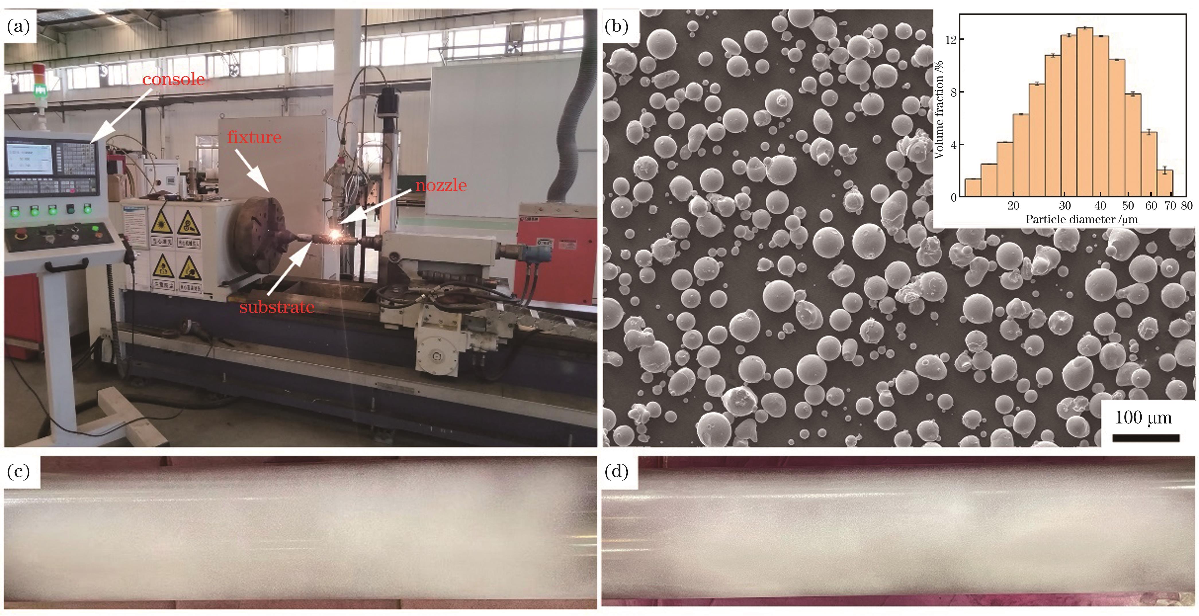
    Fig. 1. Extremely high-speed laser cladding equipment and powder raw material. (a) Extremely high-speed laser cladding equipment; (b) FeCoCrNiMo high-entropy alloy powder morphology and particle diameter distribution; (c) surface defect result of polished 316L primer; (d) surface defect result of polished 304 coating
    XRD spectra of FeCoCrNiMo powder and coating
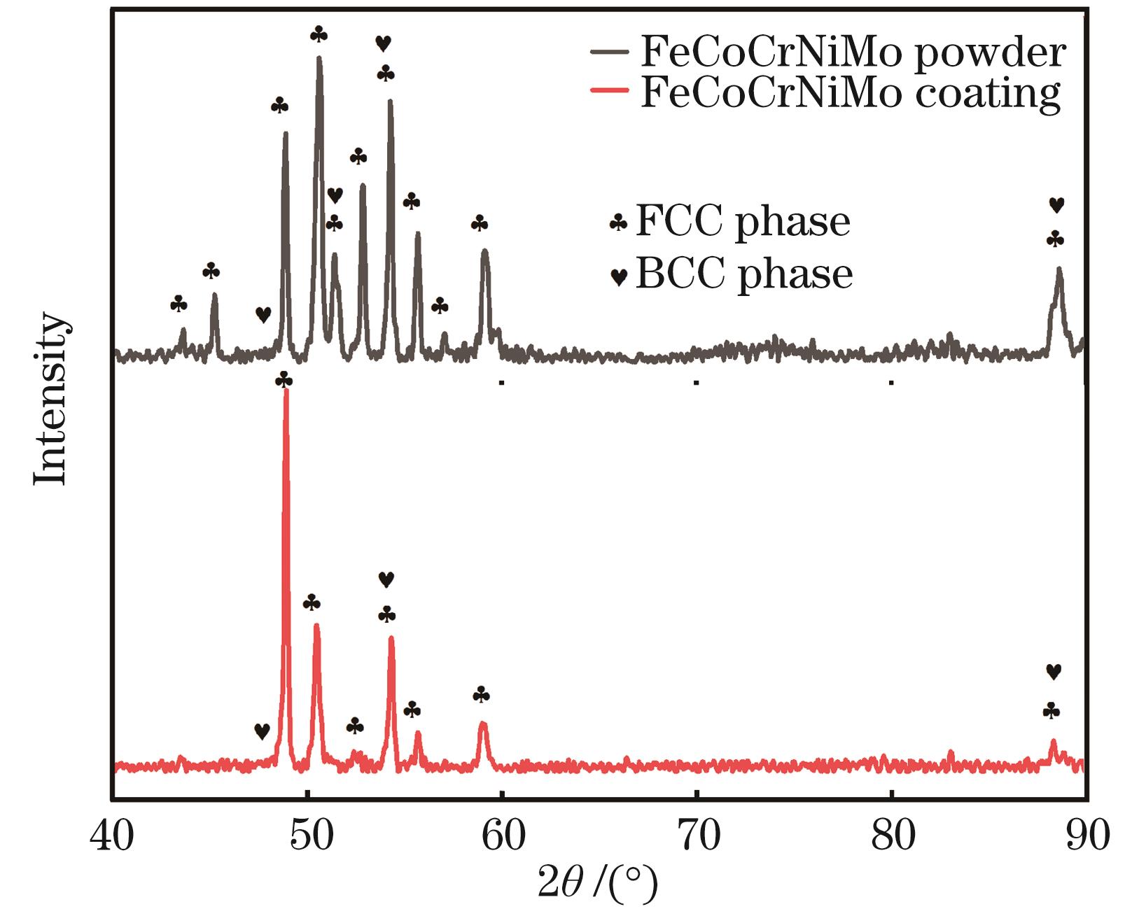
    Fig. 2. XRD spectra of FeCoCrNiMo powder and coating
    Microstructes of FeCoCrNiMo high-entropy alloy coating captured by scanning transmission electron microscopy. (a) STEM images of the bright field of the coatings and the corresponding STEM-EDS maps; (b) selected-area diffraction pattern of superlattice points of the BCC precipitated phase; (c) selected-area diffraction pattern of superlattice points of the FCC matrix phase
    Fig. 3. Microstructes of FeCoCrNiMo high-entropy alloy coating captured by scanning transmission electron microscopy. (a) STEM images of the bright field of the coatings and the corresponding STEM-EDS maps; (b) selected-area diffraction pattern of superlattice points of the BCC precipitated phase; (c) selected-area diffraction pattern of superlattice points of the FCC matrix phase
    SEM microstructure distribution of FeCoCrNiMo high-entropy alloy coatings. (a) Whole coating; (b) the top region of the coating; (c) the middle region of the coating; (d) the overlap position
    Fig. 4. SEM microstructure distribution of FeCoCrNiMo high-entropy alloy coatings. (a) Whole coating; (b) the top region of the coating; (c) the middle region of the coating; (d) the overlap position
    Detection results and optical microscopy morphology of FeCoCrNiMo high-entropy alloy coating. (a)(b) Detection results of the cracked coatings without using 316L stainless steel as a primer, where the figure (a) corresponds to the cladding parameters of P=1.5 kW and u=15 m/min and the figure (b) corresponds to the cladding parameters of P=1.5 kW and u=5 m/min; (c) detection result of the uncracked coating using 316L stainless steel as a primer, corresponding to the cladding parameters of P=1.5 kW and u=5 m/min; (d)(e) optical microscopy morphology of the cracked coatings without using 316L stainless steel as a primer, where the figure (d) corresponds to the cladding parameters of P=1.5 kW and u=15 m/min and the figure (b) corresponds to the cladding parameters of P=1.5 kW and u=5 m/min; (f) optical microscopy morphology of the uncracked coating using 316L stainless steel as a primer, corresponding to the cladding parameters of P=1.5 kW and u=5 m/min
    Fig. 5. Detection results and optical microscopy morphology of FeCoCrNiMo high-entropy alloy coating. (a)(b) Detection results of the cracked coatings without using 316L stainless steel as a primer, where the figure (a) corresponds to the cladding parameters of P=1.5 kW and u=15 m/min and the figure (b) corresponds to the cladding parameters of P=1.5 kW and u=5 m/min; (c) detection result of the uncracked coating using 316L stainless steel as a primer, corresponding to the cladding parameters of P=1.5 kW and u=5 m/min; (d)(e) optical microscopy morphology of the cracked coatings without using 316L stainless steel as a primer, where the figure (d) corresponds to the cladding parameters of P=1.5 kW and u=15 m/min and the figure (b) corresponds to the cladding parameters of P=1.5 kW and u=5 m/min; (f) optical microscopy morphology of the uncracked coating using 316L stainless steel as a primer, corresponding to the cladding parameters of P=1.5 kW and u=5 m/min
    Cross-sectional microstructure distributions of FeCoCrNiMo high-entropy alloy cracked coatings produced under different laser cladding linear velocities (No 316L stainless steel was used as a primer). (a) (c) Cross-sectional and local morphology of reticulated cracks in high-entropy alloy coating produced at a linear velocity of 15 m/min; (b) (d) cross-sectional and local morphology of stripe cracks in high-entropy alloy coating produced at a linear velocity of 5 m/min
    Fig. 6. Cross-sectional microstructure distributions of FeCoCrNiMo high-entropy alloy cracked coatings produced under different laser cladding linear velocities (No 316L stainless steel was used as a primer). (a) (c) Cross-sectional and local morphology of reticulated cracks in high-entropy alloy coating produced at a linear velocity of 15 m/min; (b) (d) cross-sectional and local morphology of stripe cracks in high-entropy alloy coating produced at a linear velocity of 5 m/min
    Microstructure distributions of FeCoCrNiMo high-entropy alloy coating fabricated by EHLC on 316L primer layer (P=1.5 kW, u=5 m/min). (a) Whole coating; (b) the top region of the coating; (c) the middle region of the coating
    Fig. 7. Microstructure distributions of FeCoCrNiMo high-entropy alloy coating fabricated by EHLC on 316L primer layer (P=1.5 kW, u=5 m/min). (a) Whole coating; (b) the top region of the coating; (c) the middle region of the coating
    Vickers hardness distribution of FeCoCrNiMo high-entropy alloy coatings produced by different linear velocities
    Fig. 8. Vickers hardness distribution of FeCoCrNiMo high-entropy alloy coatings produced by different linear velocities
    FCC phase percentage and microstructure distribution in local regions of FeCoCrNiMo high-entropy alloy coatings fabricated at different linear velocities. (a) FCC phase percentage; (b)(d) local microstructure distribution and local surface scanning results of the coating fabricated at linear velocityof 15 m/min; (c)(e) local microstructure distribution and local surface scanning results of the coating fabricated at linear velocity of 5 m/min
    Fig. 9. FCC phase percentage and microstructure distribution in local regions of FeCoCrNiMo high-entropy alloy coatings fabricated at different linear velocities. (a) FCC phase percentage; (b)(d) local microstructure distribution and local surface scanning results of the coating fabricated at linear velocityof 15 m/min; (c)(e) local microstructure distribution and local surface scanning results of the coating fabricated at linear velocity of 5 m/min
    Potentiodynamic polarisation curves and AC impedance diagram of FeCoCrNiMo high-entropy alloy and 304 stainless steel coatings. (a) Potentiodynamic polarisation curves; (b) AC impedance diagram
    Fig. 10. Potentiodynamic polarisation curves and AC impedance diagram of FeCoCrNiMo high-entropy alloy and 304 stainless steel coatings. (a) Potentiodynamic polarisation curves; (b) AC impedance diagram
    Local corrosion morphology of FeCoCrNiMo high-entropy alloy coatings following neutral salt spray experiments of different durations
    Fig. 11. Local corrosion morphology of FeCoCrNiMo high-entropy alloy coatings following neutral salt spray experiments of different durations
    ElementMass fraction /%
    Fe17.38
    Co18.34
    Cr16.16
    Ni18.26
    Mo29.85
    Table 1. Chemical composition of FeCoCrNiMo high-entropy alloy powder
    Coating type

    Laser power /

    kW

    Gas flow for transporting powder /(L/min)

    Powder flow /

    (kg/min)

    Linear velocity /

    (m/min-1

    Feed rate /

    (mm/r)

    316L primer1.8660100.3
    304 coating2.1660100.3
    Table 2. Cladding process parameters of 316L stainless steel primer and 304 stainless steel coating
    No.Gas flow for transporting powder /(L/min)Powder flow /(kg/min)Linear velocity /(m/min)Feed rate /(mm/r)
    1660150.3
    2660150.3
    3660150.3
    4660100.3
    5660200.3
    666050.3
    Table 3. Extremely high-speed laser cladding (EHLC) process parameters for FeCoCrNiMo cracked coatings without using 316L stainless steel as a primer
    ParameterValue
    Laser power /kW1.5
    Gas flow for transporting powder /(L/min)6
    Powder flow /(kg/min)60
    Linear velocity /(m/min)5
    Feed rate /(mm/r)0.3
    Table 4. EHLC process parameters for FeCoCrNiMo uncracked coating using 316L stainless steel as a primer
    CoatingEcorr /VIcorr /(A/cm2
    FeCrCoNiMo-0.3183.72×10-8
    304 stainless steel-0.4486.966×10-6
    Table 5. Fitting parameters for polarisation curves
    CoatingR1 /(Ω·cm2R2 /(Ω·cm2
    FeCrCoNiMo8.38763740
    304 stainless steel5.2713252
    Table 6. Electrochemical impedance spectrum fitting results
    Hao Xiao, Jian Huang, Peng Wang, Peixin Xu, Yifei Xu, Dongyue Zhang, Borui Du. Microstructure Evolution and Corrosion Resistance of FeCoCrNiMo High‐Entropy Alloy Coatings Fabricated via Extremely High‐Speed Laser Cladding[J]. Chinese Journal of Lasers, 2025, 52(4): 0402203
    Download Citation