
Zijian Huang, Yang Li, Yongqiang Yang, Yilong Zhang. Forming Quality and Defects of Sn-Ag-Cu Alloy by Selective Laser Melting in Air Environment[J]. Laser & Optoelectronics Progress, 2025, 62(3): 0314003
- Laser & Optoelectronics Progress
- Vol. 62, Issue 3, 0314003 (2025)
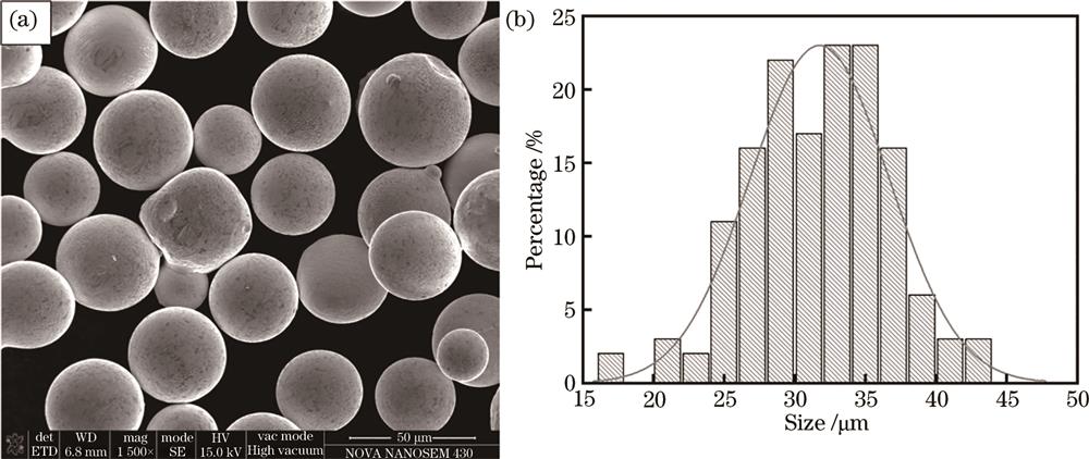
Fig. 1. Sn-3.0Ag-0.5Cu powder morphology and size distribution. (a) Powder morphology; (b) size distribution
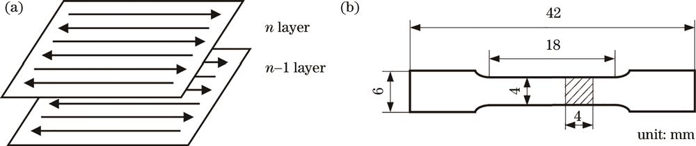
Fig. 2. Schematic of scanning strategy and tensile sample. (a) Scanning strategy; (b) tensile sample
Fig. 3. Sn-3.0Ag-0.5Cu forming samples
Fig. 4. Changes in density and various factors
Fig. 5. Energy density- density relationship of forming samples
Fig. 6. Top-surface morphologies at different process parameters. (a) 20 W-1000 mm/s-0.09 mm; (b) 20 W-800 mm/s-0.07 mm; (c) 30 W-600 mm/s-0.07 mm; (d) 35 W-900 mm/s-0.06 mm; (e) 40 W-900 mm/s-0.07 mm; (f) 40 W-700 mm/s-0.05 mm
Fig. 7. Microscope morphologies at different process parameters. (a) 20 W-1000 mm/s-0.09 mm; (b) 20 W-800 mm/s-0.07 mm; (c) 30 W-600 mm/s-0.07 mm; (d) 35 W-900 mm/s-0.06 mm; (e) 40 W-900 mm/s-0.07 mm; (f) 40 W-700 mm/s-0.05 mm
Fig. 8. Tensile properties at different powers. (a) Stress-strain curves; (b) tensile strength and elongation
Fig. 9. Fracture morphologies at different Laser powers. (a) 25 W; (b) 30 W; (c) 35 W; (d) 40 W
Fig. 10. Surface and internal morphology of samples in different environments. (a) Surface morphology with protective atmosphere; (b) surface morphology without protective atmosphere; (c) internal morphology with protective atmosphere; (d) internal morphology without protective atmosphere
Fig. 11. XRD patterns of samples in different environments
Fig. 12. SEM images of samples in different environments. (a) With protective atmosphere; (b) without protective atmosphere
Fig. 13. EDS images of samples in different environments. (a) With protective atmosphere; (b) without protective atmosphere
Fig. 14. Mechanism of spatter generation
Fig. 15. Spatter generation and residue during the forming process. (a) Spatter generation; (b) spatter residue after paving
Fig. 16. SEM image of top surface of sample in air atmosphere
Fig. 17. Influence of spatter on forming and paving. (a) Paving of the first layer; (b) residue of spatter; (c) non-fusion powder caused by spatter; (d) spatter effects on paving roller
|
Table 1. Chemical composition of Sn-3.0Ag-0.5Cu powder
|
Table 2. Factor level table
|
Table 3. Density test results
|
Table 4. Range analysis result of density
|
Table 5. Density and mechanical properties of samples in different environments


Set citation alerts for the article
Please enter your email address

© Copyright 2018-2021 | Chinese Laser Press. All Rights Reserved 沪ICP备15018463号-20