• Acta Optica Sinica
  • Vol. 43, Issue 19, 1909001 (2023)
Chi Hu1, Jin Zhang1,*, Guobin Sun1, Shilei Jiang1, and Yanyan Liu2
Author Affiliations
  • 1School of Opto-electronical Engineering, Xi'an Technological University, Xi'an 710021, Shaanxi , China
  • 2National Key Laboratory of Electromagnetic Space Security, Tianjin 300308, China
  • show less
    DOI: 10.3788/AOS230527 Cite this Article Set citation alerts
    Chi Hu, Jin Zhang, Guobin Sun, Shilei Jiang, Yanyan Liu. Study on Improving Quality of Liquid Crystal Spatial Light Modulator Holographic Reproduction Images by Phase Compensation Method of Reproduction Domain Model[J]. Acta Optica Sinica, 2023, 43(19): 1909001 Copy Citation Text show less
    Schematic diagram of spatial coordinate relationship between discrete holographic recording and reproduction
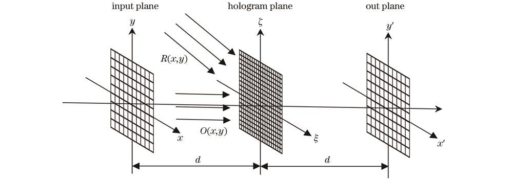
    Fig. 1. Schematic diagram of spatial coordinate relationship between discrete holographic recording and reproduction
    Schematic diagram of SLM pixel raster structure
    Fig. 2. Schematic diagram of SLM pixel raster structure
    Light intensity distribution of multistage diffraction effect in SLM holographic reproduction
    Fig. 3. Light intensity distribution of multistage diffraction effect in SLM holographic reproduction
    Schematic diagram of SLM used for holographic reproduction of multistage diffraction effect
    Fig. 4. Schematic diagram of SLM used for holographic reproduction of multistage diffraction effect
    Schematic diagram of reproduced image change after superimposing blazed grating. (a) Reproduced image without blazed grating superimposed; (b) reproduced image superimposed with vertical slot to digital blazed grating; (c) reproduced image superimposed with horizontal and vertical slot to digital blazed gratings
    Fig. 5. Schematic diagram of reproduced image change after superimposing blazed grating. (a) Reproduced image without blazed grating superimposed; (b) reproduced image superimposed with vertical slot to digital blazed grating; (c) reproduced image superimposed with horizontal and vertical slot to digital blazed gratings
    Schematic diagram of reproduced image change by phase compensation method of reproduction domain model. (a) Reproduced image without blazed grating superimposed; (b) reproduced image superimposed with vertical slot to digital blazed grating and compensation
    Fig. 6. Schematic diagram of reproduced image change by phase compensation method of reproduction domain model. (a) Reproduced image without blazed grating superimposed; (b) reproduced image superimposed with vertical slot to digital blazed grating and compensation
    Schematic diagram of reproduction domain determination
    Fig. 7. Schematic diagram of reproduction domain determination
    Calculation flow chart. (a) Flow chart of original holographic calculation; (b) flow chart of repruduction domain model phase compensation calculation
    Fig. 8. Calculation flow chart. (a) Flow chart of original holographic calculation; (b) flow chart of repruduction domain model phase compensation calculation
    Original image
    Fig. 9. Original image
    Image of reproduction domain
    Fig. 10. Image of reproduction domain
    Reproduction results of reproduction domain and reproduction results after compensation calculation. (a) Reproduction results of reproduction domain; (b) reproduction results after compensation calculation
    Fig. 11. Reproduction results of reproduction domain and reproduction results after compensation calculation. (a) Reproduction results of reproduction domain; (b) reproduction results after compensation calculation
    Inverse derivation of normalized compensation amount. (a) Original compensation amount; (b) compensation amount after inversion
    Fig. 12. Inverse derivation of normalized compensation amount. (a) Original compensation amount; (b) compensation amount after inversion
    Reproduction image after compensation. (a) Diagram of reproduced image after compensation; (b) diagram of 3D reproduced image after compensation
    Fig. 13. Reproduction image after compensation. (a) Diagram of reproduced image after compensation; (b) diagram of 3D reproduced image after compensation
    Optical path of holographic experiment for verification
    Fig. 14. Optical path of holographic experiment for verification
    Fresnel diffraction phase hologram. (a) Uncompensated phase hologram; (b) compensated phase hologram
    Fig. 15. Fresnel diffraction phase hologram. (a) Uncompensated phase hologram; (b) compensated phase hologram
    Reproduction results under different exposures
    Fig. 16. Reproduction results under different exposures
    Quality comparison curves of output results before and after improvement
    Fig. 17. Quality comparison curves of output results before and after improvement
    Chi Hu, Jin Zhang, Guobin Sun, Shilei Jiang, Yanyan Liu. Study on Improving Quality of Liquid Crystal Spatial Light Modulator Holographic Reproduction Images by Phase Compensation Method of Reproduction Domain Model[J]. Acta Optica Sinica, 2023, 43(19): 1909001
    Download Citation