• Laser & Optoelectronics Progress
  • Vol. 61, Issue 21, 2125001 (2024)
Yuzeng Zhang1,2, Zhiyuan Gao1,2,*, and Jiangtao Xu1,2
Author Affiliations
  • 1School of Microelectronics, Tianjin University, Tianjin 300072, China
  • 2Tianjin Key Laboratory of Imaging and Sensing Microelectronic Technology, Tianjin 300072, China
  • show less
    DOI: 10.3788/LOP240601 Cite this Article Set citation alerts
    Yuzeng Zhang, Zhiyuan Gao, Jiangtao Xu. Design and Simulation of High Dynamic Range Pixel with Charge Distribution and LOFIC Technology[J]. Laser & Optoelectronics Progress, 2024, 61(21): 2125001 Copy Citation Text show less
    Traditional LOFIC pixel structure
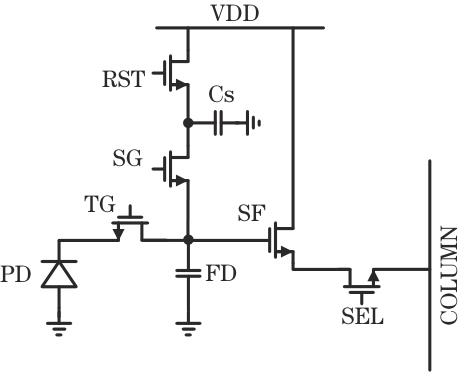
    Fig. 1. Traditional LOFIC pixel structure
    Operating time sequence of traditional LOFIC pixel
    Fig. 2. Operating time sequence of traditional LOFIC pixel
    Charge distribution LOFIC pixel structure
    Fig. 3. Charge distribution LOFIC pixel structure
    Operating time sequence of charge distribution LOFIC pixel
    Fig. 4. Operating time sequence of charge distribution LOFIC pixel
    Segmentation schematic of exposure cycle
    Fig. 5. Segmentation schematic of exposure cycle
    Potential distribution of charge overflow channel
    Fig. 6. Potential distribution of charge overflow channel
    Variation in Cs 1 node voltage with different charge distribution and dynamic refresh numbers
    Fig. 7. Variation in Cs 1 node voltage with different charge distribution and dynamic refresh numbers
    Effect of number of charge distribution and dynamic refresh on ΔVCs 1 and αimp
    Fig. 8. Effect of number of charge distribution and dynamic refresh on ΔVCs 1 and αimp
    Effect of LOFIC capacitance splitting ratio on ΔVCs 1 and αimp. (a) ΔVCs 1; (b) αimp
    Fig. 9. Effect of LOFIC capacitance splitting ratio on ΔVCs 1 and αimp. (a) ΔVCs 1; (b) αimp
    Variation of dynamic range with background noise
    Fig. 10. Variation of dynamic range with background noise
    Variation in pixel dynamic range extension with capacitance boost factor
    Fig. 11. Variation in pixel dynamic range extension with capacitance boost factor
    Variation in dynamic range upper limit with number of charge distribution and dynamic refresh and capacitance splitting ratio
    Fig. 12. Variation in dynamic range upper limit with number of charge distribution and dynamic refresh and capacitance splitting ratio
    Schematic diagram of layout design for charge distribution LOFIC pixel
    Fig. 13. Schematic diagram of layout design for charge distribution LOFIC pixel
    ParameterMeasured result of Ref. [12Simulation result
    Ref. [13Traditional LOFICThis work
    Process technology65 nm CIS StackedCMOS 110 nmCMOS 110 nmCMOS 110 nm
    Power supply voltage /V3.63.33.33.3
    Pixel size /(μm×μm)8×85×56×66×6
    HCG /[μV·(e--1130128128
    LCG /[μV·(e--145.012.04.94.9
    Capacitance boost factor7
    FWC /ke-27.783.0204.11.43×103
    Dynamic range /dB91.4102.8100.2116.8
    Dynamic range extension /dB5.516.6
    Table 1. Comparison of performance between proposed pixel structure and existing technologies
    Yuzeng Zhang, Zhiyuan Gao, Jiangtao Xu. Design and Simulation of High Dynamic Range Pixel with Charge Distribution and LOFIC Technology[J]. Laser & Optoelectronics Progress, 2024, 61(21): 2125001
    Download Citation