• Matter and Radiation at Extremes
  • Vol. 8, Issue 2, 025902 (2023)
Mengqiu Fan1,2, Shengtao Lin3, Ke Yao1, Yifei Qi3..., Jiaojiao Zhang3, Junwen Zheng1, Pan Wang3, Longqun Ni3, Xingyu Bao3, Dandan Zhou1, Bo Zhang1, Kaibo Xiao1, Handing Xia1, Rui Zhang1, Ping Li1, Wanguo Zheng1 and Zinan Wang3,a)|Show fewer author(s)
Author Affiliations
  • 1Laser Fusion Research Center, China Academy of Engineering Physics, Mianyang 621900, China
  • 2Graduate School of China Academy of Engineering Physics, Beijing 100193, China
  • 3Key Laboratory of Optical Fiber Sensing and Communications, University of Electronic Science and Technology of China, Chengdu 611731, China
  • show less
    DOI: 10.1063/5.0129434 Cite this Article
    Mengqiu Fan, Shengtao Lin, Ke Yao, Yifei Qi, Jiaojiao Zhang, Junwen Zheng, Pan Wang, Longqun Ni, Xingyu Bao, Dandan Zhou, Bo Zhang, Kaibo Xiao, Handing Xia, Rui Zhang, Ping Li, Wanguo Zheng, Zinan Wang. Spectrum-tailored random fiber laser towards ICF laser facility[J]. Matter and Radiation at Extremes, 2023, 8(2): 025902 Copy Citation Text show less
    Free-oscillation spectrum of a regenerative amplifier based on an N31 Nd:glass rod.
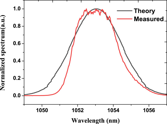
    Fig. 1. Free-oscillation spectrum of a regenerative amplifier based on an N31 Nd:glass rod.
    Experimental setup and corresponding simulation model for YRFL.
    Fig. 2. Experimental setup and corresponding simulation model for YRFL.
    Output spectrum of the YRFL with different YDF lengths.
    Fig. 3. Output spectrum of the YRFL with different YDF lengths.
    Output power of the YRFL vs pump power.
    Fig. 4. Output power of the YRFL vs pump power.
    Experiment setup for time-domain shaping and fiber amplification.
    Fig. 5. Experiment setup for time-domain shaping and fiber amplification.
    Pulse shapes after fiber amplification: (a) exponential pulse; (c) square pulse; (e) two-step pulse. The corresponding spectra are shown in (b), (d), and (f).
    Fig. 6. Pulse shapes after fiber amplification: (a) exponential pulse; (c) square pulse; (e) two-step pulse. The corresponding spectra are shown in (b), (d), and (f).
    Experimental setup of regenerative amplifier.
    Fig. 7. Experimental setup of regenerative amplifier.
    Energy curve of regenerative amplification.
    Fig. 8. Energy curve of regenerative amplification.
    Pulse shapes after regenerative amplification: (a) exponential pulse; (c) square pulse; (e) two-step pulse. The corresponding spectra are shown in (b), (d), and (f).
    Fig. 9. Pulse shapes after regenerative amplification: (a) exponential pulse; (c) square pulse; (e) two-step pulse. The corresponding spectra are shown in (b), (d), and (f).
    Measured beam quality after regenerative amplification.
    Fig. 10. Measured beam quality after regenerative amplification.
    ParameterPumpEmission
    λ (nm)9761053
    σa (m2)2.48 × 10−242.06 × 10⁻²⁶
    σe (m2)2.48 × 10−243.68 × 10⁻²⁵
    β2 (s2/m)−3 × 10−26−2.6 × 10⁻²⁶
    Γ0.00640.85
    α (m−1)0.0060.004
    Ac (m2)7.8540 × 10⁻¹¹
    Table 1. Simulation parameters for YDF.
    ParameterEmission
    λ1053 nm
    β21.64 × 10⁻²⁶ s2/m
    ɛ4.3 × 10⁻⁶ m−1
    α2.2 dB/km
    Table 2. Simulation parameters for HI 1060 FLEX fiber.
    Mengqiu Fan, Shengtao Lin, Ke Yao, Yifei Qi, Jiaojiao Zhang, Junwen Zheng, Pan Wang, Longqun Ni, Xingyu Bao, Dandan Zhou, Bo Zhang, Kaibo Xiao, Handing Xia, Rui Zhang, Ping Li, Wanguo Zheng, Zinan Wang. Spectrum-tailored random fiber laser towards ICF laser facility[J]. Matter and Radiation at Extremes, 2023, 8(2): 025902
    Download Citation