• Chinese Optics Letters
  • Vol. 23, Issue 2, 020603 (2025)
Linning Wang, Pengzhan Liu, Yingze Liang, Ziqian Qi..., Zheng Shi, Hongbo Zhu and Yongjin Wang*|Show fewer author(s)
Author Affiliations
  • GaN Optoelectronic Integration International Cooperation Joint Laboratory of Jiangsu Province, Nanjing University of Posts and Telecommunications, Nanjing 210003, China
  • show less
    DOI: 10.3788/COL202523.020603 Cite this Article Set citation alerts
    Linning Wang, Pengzhan Liu, Yingze Liang, Ziqian Qi, Zheng Shi, Hongbo Zhu, Yongjin Wang, "Mobile full-duplex wireless light communication," Chin. Opt. Lett. 23, 020603 (2025) Copy Citation Text show less
    Vision of the all-light communication network, where both mobile and fixed nodes are supported.
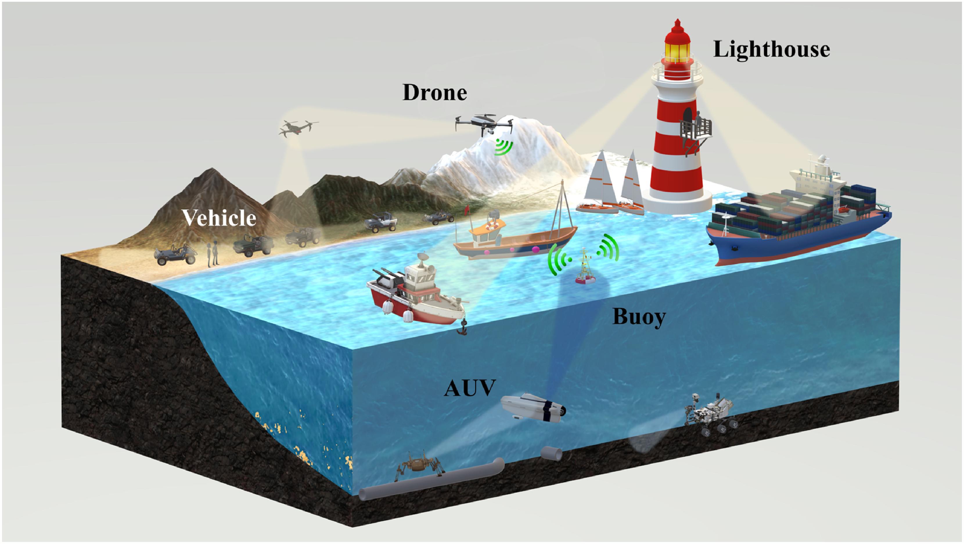
    Fig. 1. Vision of the all-light communication network, where both mobile and fixed nodes are supported.
    A full-duplex MLC link is formed by symmetrical ends, each of which consists of a light communication module, an automatic tracking module, and peripheral modules such as drones, vehicles, and power management modules.
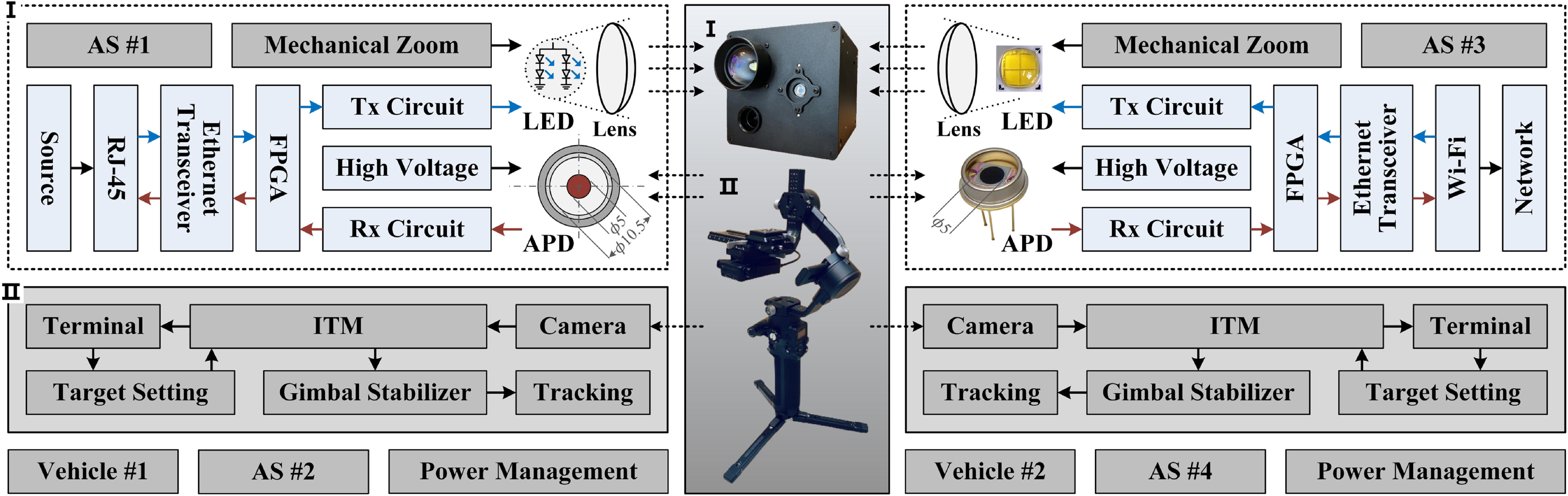
    Fig. 2. A full-duplex MLC link is formed by symmetrical ends, each of which consists of a light communication module, an automatic tracking module, and peripheral modules such as drones, vehicles, and power management modules.
    (a) Exploded view of the light communication module. (b) Physical diagram of paired MLC systems. (c) MLC using dispersed light and a wide-angle camera at a distance of 2 m. (d) Optical power distribution of the dispersed light at a distance of 20 cm. (e) MLC using focused light and a telephoto camera at a maximum distance of 46 m. (f) Optical power distribution of the focused light at a distance of 20 cm.
    Fig. 3. (a) Exploded view of the light communication module. (b) Physical diagram of paired MLC systems. (c) MLC using dispersed light and a wide-angle camera at a distance of 2 m. (d) Optical power distribution of the dispersed light at a distance of 20 cm. (e) MLC using focused light and a telephoto camera at a maximum distance of 46 m. (f) Optical power distribution of the focused light at a distance of 20 cm.
    (a) Photograph of the all-light communication network, in which full-duplex real-time video communication is demonstrated between mobile and fixed network nodes (see Visualization 1). (b) UBLC in a swimming pool. (c) Ethernet switches are used at network nodes to expand the interface capacity. (d) Real-time video communication between drones. MLCs are established under (e) codirectional motion, (f) opposite motion, and (g) circular motion, where Δθ denotes the motion angle in a period and f (Δθ) indicates the longer travel distance of the two vehicles.
    Fig. 4. (a) Photograph of the all-light communication network, in which full-duplex real-time video communication is demonstrated between mobile and fixed network nodes (see Visualization 1). (b) UBLC in a swimming pool. (c) Ethernet switches are used at network nodes to expand the interface capacity. (d) Real-time video communication between drones. MLCs are established under (e) codirectional motion, (f) opposite motion, and (g) circular motion, where Δθ denotes the motion angle in a period and fθ) indicates the longer travel distance of the two vehicles.
    Heading angles of the observed vehicle and the light beam during (a) codirectional motion, (b) opposite motion, and (c) circular motion. Optical power received at different speeds during (d) codirectional motion, (e) opposite motion, and (f) circular motion. Measured PLR, delay, and jitter values of the MLC link at different speeds during (g) codirectional motion, (h) opposite motion, and (i) circular motion. (j) Actual throughput of the MLC link during motion. Inset: BERs of the stationary link at a transmission rate of 2 Mbps. (k) Monitored TCP byte streams from the webcam to the user.
    Fig. 5. Heading angles of the observed vehicle and the light beam during (a) codirectional motion, (b) opposite motion, and (c) circular motion. Optical power received at different speeds during (d) codirectional motion, (e) opposite motion, and (f) circular motion. Measured PLR, delay, and jitter values of the MLC link at different speeds during (g) codirectional motion, (h) opposite motion, and (i) circular motion. (j) Actual throughput of the MLC link during motion. Inset: BERs of the stationary link at a transmission rate of 2 Mbps. (k) Monitored TCP byte streams from the webcam to the user.
    Linning Wang, Pengzhan Liu, Yingze Liang, Ziqian Qi, Zheng Shi, Hongbo Zhu, Yongjin Wang, "Mobile full-duplex wireless light communication," Chin. Opt. Lett. 23, 020603 (2025)
    Download Citation