• Infrared and Laser Engineering
  • Vol. 53, Issue 4, 20230713 (2024)
Mao Ye1,2, Ensi Du1,2, Qiuwei Wang1,2, and Yiqiang Zhao1,2,*
Author Affiliations
  • 1Tianjin Key Laboratory of Imaging and Sensing Microelectronic Technology, Tianjin 300072, China
  • 2School of Microelectronics, Tianjin University, Tianjin 300072, China
  • show less
    DOI: 10.3788/IRLA20230713 Cite this Article
    Mao Ye, Ensi Du, Qiuwei Wang, Yiqiang Zhao. High-precision temperature control system design for laser diode[J]. Infrared and Laser Engineering, 2024, 53(4): 20230713 Copy Citation Text show less
    The overall architecture of the digital-analog hybrid temperature control system
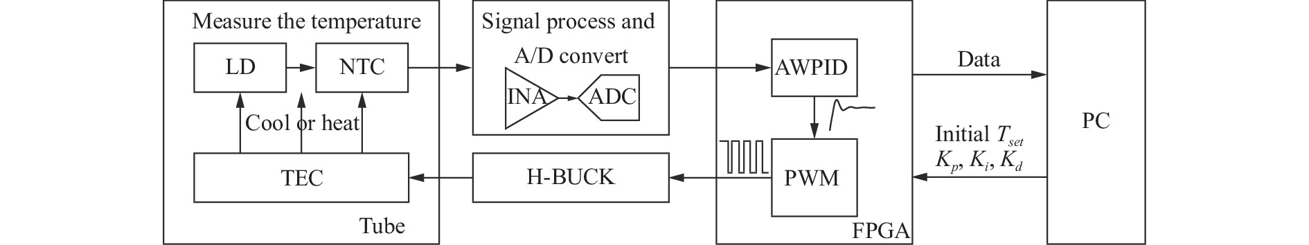
    Fig. 1. The overall architecture of the digital-analog hybrid temperature control system
    Temperature measurement circuit
    Fig. 2. Temperature measurement circuit
    Implementation of variable zero temperature control
    Fig. 3. Implementation of variable zero temperature control
    Iterative and multi-objective optimization implementation methods
    Fig. 4. Iterative and multi-objective optimization implementation methods
    Accuracy of the variable zero point temperature control method at different iterations
    Fig. 5. Accuracy of the variable zero point temperature control method at different iterations
    Control flow chart of AWPID
    Fig. 6. Control flow chart of AWPID
    H-BUCK drive circuit with T-capacitor network
    Fig. 7. H-BUCK drive circuit with T-capacitor network
    (a) Overall physical diagram of the overall architecture of the temperature control system; (b) Schematic diagram of a LD package; (c) Schematic diagram of the integrated device inside the LD package
    Fig. 8. (a) Overall physical diagram of the overall architecture of the temperature control system; (b) Schematic diagram of a LD package; (c) Schematic diagram of the integrated device inside the LD package
    FPGA resource usage
    Fig. 9. FPGA resource usage
    Temperature control system temperature control function test
    Fig. 10. Temperature control system temperature control function test
    Comparison of different PID controls
    Fig. 11. Comparison of different PID controls
    The architecture of the level-2 TEC temperature control system
    Fig. 12. The architecture of the level-2 TEC temperature control system
    (a) Turn on LD stability testing; (b) Local enlargement of stability test results
    Fig. 13. (a) Turn on LD stability testing; (b) Local enlargement of stability test results
    Sensor typeSizeSensitivityLinearitySelf-heating
    Note: The number of "+" indicates the degree of strength of the item, while the number of "-" indicates the degree of weakness.
    Thermistor++++--++
    RTD+--+-
    TMP102-++++
    AD592--+++
    Table 1. Common temperature sensor performance
    Tset/℃${T_H} - {T_C}$/℃${Q_{passive}}$/mW
    −4582761.47
    −2562580.69
    −542397.06
    037350.66
    1522310.11
    2512115.22
    3518171.89
    5538367.09
    7558567.27
    Table 2. Summary of passive heat dissipation power under different set temperatures
    T/℃Zero/℃Control typeAccuracy/℃Stable* time/sOver-shoot
    Note: *The stabilization time is defined as the total time from the start of temperature control until the temperature stabilizes at the required accuracy
    30-Heat0.0202301.5%
    2529Heat0.0197270.5%
    20-Cool0.0197281.4%
    Table 3. Temperature control function test results
    T/℃Zero/℃Accuracy/℃Mean/℃Std/℃Fixed zero accuracy/℃
    −45−330.0212−44.99920.02190.1951
    −250.0217−25.00090.02280.0629
    −15−120.0206−14.999870.02210.0409
    −50.0212−4.99910.02170.0295
    580.01944.99810.02130.0238
    150.021314.99970.02210.0216
    25290.019125.00130.01120.0220
    300.019630.00170.01400.0230
    350.020635.00050.01340.0246
    45490.019545.00010.01170.0296
    550.020854.99850.02350.0376
    65700.019565.00000.01240.0495
    750.020774.99910.02390.0663
    Table 4. Accuracy testing and comparison with single zero point accuracy