
Sheng DING, Kai NING, Binxia YUAN, Weiguo PAN, Shibin YIN, Jianfeng LIU. Durability of Fe-N/C Catalysts with Different Nanostructures for Electrochemical Oxygen Reduction in Alkaline Solution [J]. Journal of Inorganic Materials, 2020, 35(8): 953
- Journal of Inorganic Materials
- Vol. 35, Issue 8, 953 (2020)
Abstract
Fuel cells are known as the replacement of fossil fuels for their great power density, high efficiency, environmental protection, and reliability. The electrochemical oxygen reduction plays an important role in polymer electrolyte membrane fuel cells (PEMFCs). The sluggish ORR in PEMFC cathode requires highly activated catalysts, among which the platinum-based materials are mainly used. However, platinum-based catalysts are generally expensive, rare and nondurable. In addition, carbon corrosion, platinum dissolution, maturation and shedding of nanoparticles lead to the deterioration of Pt-based catalyst over time. All of these limited the widespread commercial application of PEMFCs.
One of the main methods to solve these problems is to replace platinum-based catalysts with non-noble metal catalysts (NNMC, such as Fe-N/C catalysts). In Fe-N/C catalysts, various active sites have been studied, including quaternary nitrogen or pyridine nitrogen[
This study aims to reveal the effect of nanostructures of Fe-N/C catalysts on ORR activity. Hence, dicyandiamide and melamine were utilized to regulate the micromorphology of N-doped carbon nanotubes (N-CNTs) and core-shell structure. This study opens up new avenues to enhance the electrochemical activity of ORR catalysts and provides a feasible method for the rational design of catalysts in the future.
1 Experimental
1.1 Synthesis of Fe-N/C catalysts and Pt-decorated carbon black (Pt/CB)
0.2 g KB (Ketjenblack, EC-600JD, Lion Co., Ltd) was dispersed in 50 mL absolute alcohol and ultrasonic for 30 min. 2.02 g iron (III) nitrate nonahydrate (Fe(NO3)3·9H2O, Wako) was added and stirred at 25 ℃ for 24 h. The product was filtered and dried at 60 ℃. The receiving powder was ground with 2.0 g dicyandiamide (Aladdin Industrial Co., Ltd) until turning grizzle, and then pyrolyzed at 900 ℃ for 1 h (N2, 50 mL·min-1, 5 ℃·min-1). The product was labeled as FeNC-DCDA. 2.0 g melamine (Aladdin Industrial Co., Ltd) was used to replace dicyandiamide with the same preparation process. The resulting powder was labeled as FeNC-MM. Pt/C was prepared according to the literature [9-10].
1.2 Materials characterization
The samples were characterized by field emission scanning electron microscope (FE-SEM, HITACHI S-4800), transmission electron microscope (TEM, Tecnai F20 S-TWIN, FEI), X-ray powder diffraction (XRD, BRUKER D8 ADVANCE Diffractometer, Bruker, with Cu Kα radiation), and X-ray photoelectron spectroscope (XPS, ESCALAB 250Xi, Thermo scientific).
The experimental methods for electrochemical characterization including electrode preparation, half-cell measurements and load-cycling durability measurements were listed in the supporting materials.
2 Results and discussion
2.1 Physical and chemical properties
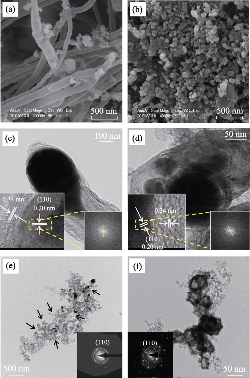
The morphologies of the samples were detected by SEM and TEM. FeNC-DCDA shows an interconnected and parallel CNT framework, which envelope the Fe nanoparticles (Fig. 1(a)). The CNTs structures serve as fibrous shells to prevent the aggregation of Fe particles. They also enhance the conductivity and electrochemical activity. The Fe nanoparticles distributed in the nodes and tips of CNTs are separated by wall, and thus keep the moderate size. FeNC-MM (Fig. 1(b)) exhibits nanoparticle- like micromorphology, similar to KB matrix.
![]()
Figure 1.SEM images of (a) FeNC-DCDA and (b) FeNC-MM; HRTEM images of (c) FeNC-DCDA and (d) FeNC-MM with insets showing corresponding FFT patterns; TEM images of (e) FeNC-DCDA and (f) FeNC-MM with insets showing corresponding SAED images
TEM images of FeNC-DCDA (Fig. 1(c, e)) show that some nanoparticles are embedded or attached to CNTs. These structures enhance the mass transfer rates of reactants and products. The split points in the fast Fourier transform (FFT) pattern from HRTEM images (insets in Fig. 1(c-d)) demonstrate that the lattice spacing of dark nanoparticle is 0.20 nm, corresponding to the (110) crystal plane of the metallic Fe phase. The lattice spacing of the outer graphene layers is 0.34 nm, corresponding to the (002) crystal plane of graphite carbon. The Fe nanocrystal of FeNC-MM (Fig. 1(d)) is coated by thick graphene layers through the closer observation of a single nanoparticle. Further observation of the single nanotube (Fig. S1(a)) shows that the Fe nanoparticles are encapsulated by the graphite layers and located at the tips and nodes of N-doped CNTs, indicating the tip-growth mechanism. Fig. S1(a-b) show that the large Fe nanoparticles split into smaller segments during the in-situ growth of CNTs, which controls the size of graphene- encapsulated metallic Fe-Fe3C nanocrystals so as to avert the formation of larger nanoparticles. The fact that the CNTs in FeNC-DCDA (the arrows in Fig. 1(e)) are rarely observed in FeNC-MM (Fig. 1(f)) reveals that the melamine cannot support the formation of CNTs. Meanwhile, dark areas in FeNC-MM are much larger than those of Fe nanoparticles encased in CNTs for FeNC-DCDA (Fig. 1(e-f)). The selected area electron diffraction (SAED) patterns (insets in Fig. 1(e-f)) also demonstrate the existence of Fe (110) crystal plane, which is consistent with FFT patterns in Fig. 1(c-d).
Fig. 2(a) shows XRD patterns for FeNC-DCDA and FeNC-MM. A prominent C (002) peak of FeNC-MM locates at 2θ=26°, indicating certain degree of graphitization. A strong diffraction peak at 2θ=44.7° attributed to the Fe (110) crystal plane (JCPDS 87-0721) matches the crystal diffraction of metallic α-Fe, as well as 2 noteworthy peaks at 2θ=65° and 82°. These peaks reveal that the carbon shells coated on the Fe nanoparticles successfully protect the metallic Fe from oxidization. Several small peaks in FeNC-MM (2θ=42.9°, 43.7°, 44.6°, 45°) suggest the existence of Fe3C (JCPDS 35-0772). Several smaller peaks from 2θ=30° to 40° are likely assigned to the iron oxides nanoparticles which have not been reduced during the annealing process.
![]()
Figure 2.XRD patterns (a), XPS wide scan (b), XPS C1s spectra (c), XPS N1s spectra (d) for FeNC-DCDA and FeNC-MM
The XRD pattern of FeNC-DCDA is similar to that of FeNC-MM. However, the low intense peaks from 2θ=42° to 45° are indistinguishable except the one located at 2θ=43.7° due to the small size of Fe particles and N-CNTs structure (Fig. 1(e-f)).
Fig. 2(b-d) show XPS spectra of the catalysts, indicating that nitrogen atoms are successfully doped into the carbon framework of FeNC-DCDA and FeNC-MM materials. FeNC-DCDA and FeNC-MM display N1s peaks at around 398 eV with nitrogen contents of 0.25at% and 1.85at% (Table S1).
XPS C1s curves of FeNC-DCDA and FeNC-MM (Fig. 2(c)) both center at 284.7 eV and have a tail at higher binding energy. The C1s spectra (Fig. 2(c)) are deconvoluted into binding energies that are attributed to C=C (284.75 eV), C-O (285.4 eV), C-N/C=O (287.28 eV) and plasmon (290.99 eV), respectively[
Four peaks in N 1s XPS spectra of FeNC-DCDA and FeNC-MM (Fig. 2(d)) correspond to N-C (398.71 eV), iron nitrides (399.82 eV), graphitic nitrogen (401.38 eV) and oxygenated nitrogen (403.51 eV)[
The signals at around 398.68 and 401.26 eV are assigned to N-C and graphitic nitrogen, respectively. The different nitrogen sources for both catalysts result in the different graphitic nitrogen contents between FeNC- DCDA and FeNC-MM. The graphitic nitrogen content for FeNC-DCDA is significantly higher than that for FeNC-MM. Intensification of the peak at ~400 eV is attributed to the increase of Fe-Nx content (Table S2).
2.2 Electrochemical characterization
The electrochemical activity was evaluated by cyclic voltammetry (CV) and linear sweep voltammetry (LSV) in O2-saturated and N2-saturated 0.1 mol·L-1 KOH. FromLSV curves (Fig. 3(a)), the onset potential of Pt/C is 1.065 V (vs RHE) and the mass diffusion-limited current density is -5.14 mA·cm-2 at 1600 r·min-1. The onset potential for KB is 0.89 V(vs RHE), and the mass diffusion-limited current density is -2.73 mA·cm-2, which are much lower than those of Pt/C. For FeNC-DCDA, the onset potential is 1.055 V(vs RHE) which is only 10 mV lower than Pt/C, and the mass diffusion-limited current density is -4.3 mA·cm-2. FeNC-MM also displays high initial activity with the onset potential of 1.02 V(vs RHE) and the mass diffusion-limited current density of -4.44 mA·cm-2 which are close to those of Pt/C, but lower than FeNC-DCDA. The half-wave potentials for KB, FeNC-MM, FeNC-DCDA, and Pt/C are 0.697, 0.792, 0.857, and 0.865 V(vs RHE) respectively which are consistent with their onset potential trends. The mass activity of the Pt/C is defined as the kinetically controlled current per gram of Pt (i.e. A·$\text{g}_{\text{Pt}}^{-\text{1}}$). For non-noble catalysts, the mass activity is defined as the kinetically controlled current per gram of catalyst. Thus, the mass activities are calculated as 2.12 A·$\text{g}_{\text{KB}}^{-\text{1}}$, 18.84 A·$\text{g}_{\text{FeNC-DCDA}}^{-\text{1}}$, and 17.32 A·$\text{g}_{\text{FeNC-MM}}^{-\text{1}}$and 1017.65 A·$\text{g}_{\text{Pt}}^{-\text{1}}$ at 0.77 V(vs RHE). These results show that the FeNC- DCDA possesses higher onset potential, half-wave potential and mass activity than FeNC-MM, indicating the better electrochemical activity.
![]()
Figure 3.LSV curves (a), CV curves (b), H2O2 yield (c) and electron transfer number (d) for Pt/C, FeNC-DCDA, FeNC-MM and KB in O2-saturated 0.1 mol·L-1 KOH at 1600 r·min-1
The CV curve of Pt/C (Fig. 3(b)) displays an oxidation/ reduction peak of PtOx with potential above 0.6 V(vs RHE) and a double-layer capacitance region ranging from 0.5 to 0.6 V(vs RHE). These data are close to the results reported in the literature [13], suggesting that the as-prepared Pt/C catalyst is suitable for reference. The CV curves of both NNMCs are quasi-rectangular and display no significant redox peaks under O2 conditions, which are the typical characteristics of high specific surface area for carbon materials[
All of the resulting metal-containing materials are catalyzed by quasi-four-electron-transfer pathway (Fig. 3(c-d)), while the FeNC-DCDA catalyst owns a higher proportion of 4-electron ORR than FeNC-MM. This indicates that the ratio of 4-electron ORR catalytic sites is much lower in the absence of N-CNTs. The higher initial performance of FeNC-DCDA catalyst may be attributed to its more uniform distribution of the internal Fe-Fe3C nanocrystals which boosts the catalytic activity of Fe-Nx active sites on the outer surface of the carbon shell[
2.3 Load-cycling durability
It is critical to maintain activity throughout the service life of the fuel cell. Hence, the durability tests of NNMCs are conducted and compared with Pt/C catalyst in this study.
Fig. 4(a-b) are CV and LSV curves of the durability tests for the Pt/C catalyst. During the experiment, the oxidation/ reduction peak and hydrogen adsorption/desorption of platinum are significantly reduced, and the half-wave potential decreases by 30 mV. This can be contributed to the decline of electrochemical surface area for the aggregation of platinum nanoparticles and the carbon support dissolution or detachment[
![]()
Figure 4.CV curves in N2-saturated 0.1 mol·L-1 KOH and LSV curves in O2-saturated 0.1 mol·L-1 KOH of the catalysts for 30000 load potential cycles(a-b) Pt/C; (c-d) FeNC-MM; (e-f) FeNC-DCDA
The area of the CV curves for FeNC-MM (Fig. 4(c)) shows a significant drop during the durability test, revealing the change of double-layer capacitance which is associated with the durability of the carbon support. Furthermore, the half-wave potential decreases significantly by 72 mV (Fig. 4(d)), indicating relatively poor cycling performance compared to Pt/C catalyst.
After 30000 cycles, the change in CV and LSV curves for FeNC-DCDA (Fig. 4(e-f)) is negligible, indicating its stable ORR activity. The half-wave potential hardly changed throughout the durability test compared with Pt/C catalyst. This indicates that the active sites in FeNC-DCDA are more stable than those in Pt/C catalyst or somehow prevents electrochemical degradation.
The maximum current density after 30000 cycles of Pt/C, FeNC-MM, and FeNC-DCDA (Fig. S3) dropped to 87.5%, 94.1%, and 95.8% of their initial value. Pt/C has the highest initial activity but is unstable during 30000 cycles. FeNC-MM also presents high initial activity, but degrades at a relatively fast rate after 10000 cycles. Its activity is also unstable in the remaining potential cycles. The initial activity of FeNC-DCDA is slightly lower than Pt/C, but the degradation is negligible, indicating that the FeNC-DCDA is an applicable catalyst for ORR catalysis in alkaline medium.
3 Conclusions
In summary, two Fe/N-C catalysts with different nitrogen sources were synthesized and compared to reveal the influence of nitrogen sources on ORR activity. It was found that nitrogen sources affect the nanostructures, micromorphology and electrochemical performance for Fe/N-C catalysts. The analytical results from SEM, TEM, XRD, and XPS confirm the FeNC-DCDA with moderate size of Fe-Fe3C@C nanocrystals, higher contents of graphitic nitrogen and Fe-Nx species possesses higher half-wave potential (0.857 V(vs RHE), only 8 mV lower than that of Pt/C) and better durability (the maximum current density retention is 95.8% after 30000 cycles). These characteristics make FeNC-DCDA a catalyst more suitable for ORR in alkaline solution than Pt/C catalyst.
Supporting materials
[1] OHMA A, SHINOHARA K, IIYAMA A, et al. Membrane and catalyst performance targets for automotive fuel cells by FCCJ membrane, catalyst, MEA WG. ECS Transactions, 2011, 41(1): 775-784.
The working electrode was prepared based on the standard protocol of Fuel Cell Commercialization of Japan (FCCJ)[
[2] LYTH S M, NABAE Y, ISLAM N M, et al. Electrochemical oxygen reduction activity of carbon nitride supported on carbon black. Journal of The Electrochemical Society, 2011, 158(2): B194-B201.
Half-cell measurements were carried out on rotating ring disk electrode (RRDE) by an electrochemical device (Hokuto Denko Corp., Ltd, HR-301). A platinum-wire (carbon rod in durability tests) was used as the counter electrode, and an Ag/AgCl electrode was used as the reference electrode. All tests were carried out in N2-saturated or O2-saturated 0.1 mol·L-1 KOH solution at 25 ℃. The received voltages were recalculated relative to a reversible hydrogen electrode (RHE).
[3] LIU J F, TAKESHI D, SASAKI K, et al. Defective graphene foam: a platinum catalyst support for PEMFCs. Journal of The Electrochemical Society, 2014, 161(9): F838-F844.
The CV curves were obtained within 0-1.2 V(vs RHE) at a scan rate of 50 mV·s-1 in N2-saturated 0.1 mol·L-1 KOH solution. The number of electron transfer (n) and the H2O2 yield during the process of oxygen reduction reaction (ORR) were detected by rotating ring disk electrode (RRDE). The LSV curves were obtained within 1.2-0.2 V(vs RHE) at a scan rate of 10 mV·s-1 in O2-saturated solution with different rotate speeds (400, 900, 1600, and 2500 r·min-1). The LSV curves in Fig. 3(a) were obtained by eliminating the blank current curves recorded in the N2-saturated solution in order to eliminate the effects of residual oxygen in electrolyte solution.
[4] ZADICK A, DUBAU L, SERGENT N, et al. Huge instability of Pt/C catalysts in alkaline medium. ACS Catalysis, 2015, 5(8): 4819-4824.
[5] SHENG W C, GASTEIGER H A, SHAO-HORN Y. Hydrogen oxidation and evolution reaction kinetics on platinum: acid vs alkaline electrolytes. Journal of The Electrochemical Society, 2010, 157(11): B1529-B1536.
The H2O2 yield and number of electron transfer (n) were calculated by the equations below:
[6] THORUM M S, HANKETT J M, GEWIRTH A A. Poisoning the oxygen reduction reaction on carbon-supported Fe and Cu electrocatalysts: evidence for metal-centered activity. The Journal of Physical Chemistry Letters, 2011, 2(4): 295-298.
Where ${{I}_{\text{d}}}$ is disk current, ${{I}_{\text{r}}}$ is ring current and N, 0.4735, is the current collection efficiency of the Pt ring carbon disk electrode.
U.S. Department of Energy (U.S. DOE) and FCCJ have clearly defined polymer electrode membrane fuel cell (PEMFC) cycle durability measurement protocols. The PEMFC durability protocols contains start-stop tests to detect carbon corrosion and a duty cycle durability test to evaluate Pt stability. However, the potential of carbon corrosion in alkaline media is different from that in acidic media, which causs that the PEMFC durability protocols do not fit anion exchange membrane fuel cell (AEMFC)[
To better support the above conclusions, two control experiments were performed. (1) The catalyst FeNC-DCDA was immersed in 0.5 mol·L-1 H2SO4 for 12 h at 60 ℃ to remove Fe particles. The Fe-Fe3C nanocrystals in the FeNC-DCDA catalyst were reduced, and the ORR activity of acid-leached FeNC-DCDA catalyst was significantly decreased. The half-wave potential at 0.797 V(vs RHE) was 60 mV lower than the initial electrochemical activity (Fig. S2(a)). The microstructure of Fe-Fe3C nanocrystals lead to high ORR activity of the catalyst. (2) It is well known that SCN- ion can poison Fe-Nx active sites in ORR[
![]()
Figure S1.HRTEM images of FeNC-DCDA
![]()
Figure S2.LSV curves of as-prepared and acid-leached FeNC-DCDA measured in O2-saturated 0.1 mol·L-1 KOH (a) and LSV curves of SCN- poisoned FeNC-DCDA measured in O2-saturated 0.1 mol·L-1 KOH (1600 r·min-1, 10 mV s-1) (b)
![]()
Figure S3.Comparison of maximum current densities of catalysts before and after the durability tests
| Compositon | FeNC-DCDA/at% | FeNC-MM/at% |
|---|---|---|
| Carbon | 97.05 | 96.14 |
| Nitrogen | 0.25 | 1.85 |
| Oxygen | 2.21 | 1.54 |
| Iron | 0.49 | 0.48 |
Table 1.
Elemental compositions of Fe-N/C catalysts synthesized with different nitrogen sources obtained from XPS analysis
| Catalyst | N-C | Fe-N | Graphitic nitrogen | Oxygenated nitrogen | ||||
|---|---|---|---|---|---|---|---|---|
| Position/eV | Fraction/% | Position/eV | Fraction/% | Position/eV | Fraction/% | Position/eV | Fraction/% | |
| FeNC-DCDA | 398.71 | 35.66 | 399.82 | 10.02 | 401.38 | 24.79 | 403.51 | 29.52 |
| FeNC-MM | 398.68 | 34.54 | 400.07 | 8.4 | 401.26 | 13.2 | 404.2 | 43.86 |
Table 2.
Nitrogen contents and deconvoluted N 1s peak positions in Fe-N/C catalysts from XPS data
References
[12] JOSÉ H ZAGAL, FETHI BEDIOUI, JEAN-POL DODELET. N4-Macrocyclic Metal Complexes. New York: Springer, 83-147(2006).


Set citation alerts for the article
Please enter your email address

© Copyright 2018-2021 | Chinese Laser Press. All Rights Reserved 沪ICP备15018463号-20