• Laser & Optoelectronics Progress
  • Vol. 62, Issue 3, 0316002 (2025)
Chenxin Wang*, Yonggang Zou, Jie Fan, Linlin Shi..., Yuxin Yue, Yingmin Song and Hongjin Liang|Show fewer author(s)
Author Affiliations
  • State Key Laboratory of High Power Semiconductor Lasers, Changchun University of Science and Technology, Changchun 130022, Jilin , China
  • show less
    DOI: 10.3788/LOP240999 Cite this Article Set citation alerts
    Chenxin Wang, Yonggang Zou, Jie Fan, Linlin Shi, Yuxin Yue, Yingmin Song, Hongjin Liang. Thermal Characteristics Analysis of Multi-Material Composite Heat Sink Structure Based on VCSEL Array[J]. Laser & Optoelectronics Progress, 2025, 62(3): 0316002 Copy Citation Text show less
    Traditional structure schematic diagram
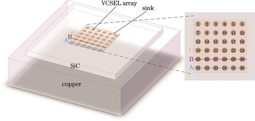
    Fig. 1. Traditional structure schematic diagram
    Temperature distribution curve diagrams of VCSEL array along different paths with different groove filling materials. (a) Path B; (b) path C
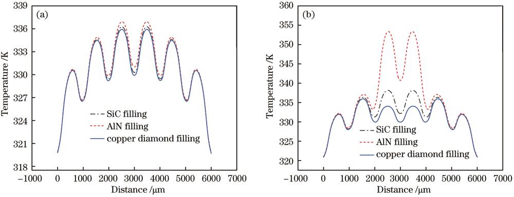
    Fig. 2. Temperature distribution curve diagrams of VCSEL array along different paths with different groove filling materials. (a) Path B; (b) path C
    Temperature distribution curve diagrams of VCSEL array along different paths under different groove depths.(a) Path B; (b) path C
    Fig. 3. Temperature distribution curve diagrams of VCSEL array along different paths under different groove depths.(a) Path B; (b) path C
    Temperature distribution curve diagrams along paths A, B, and C for devices with grooves filled with copper-diamond material underneath units 15, 16, 21, and 22
    Fig. 4. Temperature distribution curve diagrams along paths A, B, and C for devices with grooves filled with copper-diamond material underneath units 15, 16, 21, and 22
    Simplified schematic diagram of novel multi-material composite heat sink
    Fig. 5. Simplified schematic diagram of novel multi-material composite heat sink
    Device temperature distribution diagrams under two different heat dissipation structures. (a) Traditional structure; (b) optimized structure
    Fig. 6. Device temperature distribution diagrams under two different heat dissipation structures. (a) Traditional structure; (b) optimized structure
    Temperature distribution curves along paths A, B, and C for devices encapsulated with traditional heat dissipation structure and new heat dissipation structure
    Fig. 7. Temperature distribution curves along paths A, B, and C for devices encapsulated with traditional heat dissipation structure and new heat dissipation structure
    P-I characteristic curves under different thermal resistances
    Fig. 8. P-I characteristic curves under different thermal resistances
    ItemCross-section dimension /(μm×μm)Thickness /μmThermal conductivity /(W/m·K)
    Chip1000×100012055
    Heat source300×300555
    SiC16000×160001000/2000490
    Square copper diamond1000×1000500/1000/2000811
    Cylindrical copper diamond800×80070/280811
    AlN800×80010/30/88180
    Copper20000×200005000398
    Table 1. Structural and material parameters[13-17]
    Chenxin Wang, Yonggang Zou, Jie Fan, Linlin Shi, Yuxin Yue, Yingmin Song, Hongjin Liang. Thermal Characteristics Analysis of Multi-Material Composite Heat Sink Structure Based on VCSEL Array[J]. Laser & Optoelectronics Progress, 2025, 62(3): 0316002
    Download Citation