
Zaiwei Cai, Zihao Li, Yingtao Zhang, Chiyi Wei, Hao Tian, Molei Hao, Xiaoming Wei, Zhongmin Yang, "High repetition rate ultrafast laser-structured nickel electrocatalyst for efficient hydrogen evolution reaction," Adv. Photon. Nexus 2, 056009 (2023)
- Advanced Photonics Nexus
- Vol. 2, Issue 5, 056009 (2023)
Abstract
Keywords
1 Introduction
Due to the growth of the global population and the development of society, the consumption of exhaustible fossil fuels is increasing, which leads to environmental deterioration, global warming, and the energy crisis.1 Therefore, there is an urgent need to find a replacement for nonrenewable energy sources. Hydrogen is an attractive energy carrier due to its high-energy density, clean property, and high availability.2,3 As a sustainable hydrogen production strategy, electrolysis of water has achieved large-scale and mature commercial hydrogen production.3 However, due to the high cost of the efficient noble metal hydrogen evolution reaction (HER) electrocatalysts, such as platinum (Pt),4 ruthenium (Ru),5 and iridium (Ir),6 searching for non-noble metal-based electrocatalysts is significantly important.7 As one of the most promising candidates for non-noble metal electrocatalyst, nickel (Ni) possesses the lowest hydrogen adsorption free energy and the highest HER exchange current density among non-noble metals in alkaline solution8 and has the advantages of high conductivity, high oxidation resistance, as well as abundant reserve,1 and thus draws great interest.
Enlarging the surface area and subsequently increasing the number of electrochemically active sites on the electrocatalyst is an important strategy for improving the performance of the electrocatalyst.9 Common methods to increase the surface area of electrocatalysts include chemical coating,10 electrodeposition,11 electrospraying,12 a combination of mechanical alloying and chemical leaching,13 and template methods.14,15 However, micro/nanomaterials prepared by chemical coating and electrospraying possess low structural stability, template method produces polluting byproducts, and electrodeposition only generates irregular structures,1 while the combination of mechanical alloying and chemical leaching is relatively time- and cost-consuming. An ultrafast laser, with its ultrashort pulse width and high peak power, enables extreme processing conditions,16 making it a novel way to modify the optical,17
The high repetition rate laser with intrapulse repetition rate in the order of gigahertz is a novel tool for laser structuring, which can reduce the minimum average power required to reach the ablation threshold of a material.39 When the repetition rate of a pulsed laser is high enough, heat accumulation occurs between two neighboring pulses within the irradiated area, which is an effect absent in low repetition rate laser processing. When a high repetition rate laser operates in the burst mode through modulation, its burst envelope, burst duty ratio, and interburst repetition rate are all adjustable. Therefore, the high repetition rate ultrafast laser possesses even more degrees of freedom and thus can endow the substrate with an even greater diversity of micro/nanostructures. This is an incomparable advantage over pulsed lasers with low repetition rate. Here we report for the first time, we believe, using a homemade modulable high repetition rate ultrafast laser working under different conditions to generate different micro/nanostructures on Ni electrodes. The surface morphology and the electrochemical properties of the untreated and laser-structured electrodes are studied. Our results show that by tuning the parameters of laser structuring, self-organized worm-shaped microstructures and parallel grooves can be formed under low scan speed, high scan number, and high-pulse fluence, respectively. Compared with bare Ni electrodes, the electrocatalytic performances of the laser-structured Ni electrodes are all significantly improved.
Sign up for Advanced Photonics Nexus TOC. Get the latest issue of Advanced Photonics Nexus delivered right to you!Sign up now
2 Results and Discussion
2.1 Laser Structuring Parameters
To take full advantage of the multi-degree-of-freedom characteristics of the modulable high repetition rate laser, three groups of drastically different laser structuring conditions were applied to fabricate three groups of samples, denoted as low scan speed group (S), high scan number group (N), and high-pulse fluence group (F). Among them, the low scan speed group has the highest deposited energy per unit area because of the smallest scan pitch distance and the lowest scan speed. Combined with the lowest incident laser power, the transversal mass transfer on these samples is promoted. The samples in this group are labeled S-2, S-4, and S-6 according to their scan numbers. The scan numbers of the high scan number group are 2 orders of magnitude higher than the other groups, which is beneficial for the longitudinal-wise development of the microstructures. The samples are labeled N-50, N-150, and N-250, according to the scan speeds of the laser during structuring. The high-pulse fluence group was structured with the highest incident laser power as well as the highest pulse fluence, and therefore theoretically the highest ablation rate. The samples are labeled F-1, F-2, and F-3 according to their scan numbers. Among the three experimental laser parameters, the low scan speed group was structured by the lowest average laser power, which corresponds to a fluence right above ablation threshold. Therefore, the ablation threshold of Ni in this experiment can be calculated to be
2.2 Surface Morphology and Composition
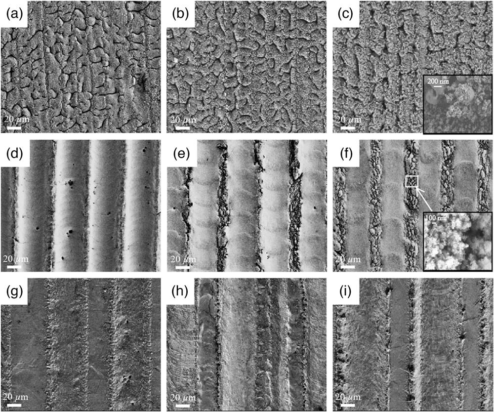
Scanning electron microscopy (SEM) was applied to study the surface morphology of different samples. As shown in Figs. 1(a)–1(c), all samples in the low scan speed group consisted of self-organized worm-shaped microstructures with redeposited nanoparticle aggregates on top;41 a zoom-in view of hierarchical micro/nanostructure is shown in the inset of Fig. 1(c). The highest deposited energy per unit area and the lowest incident laser power lead to the large heat dissipation distance and long heat relaxation time, which allow continuous material heating without ablation and in-plane material transfer resulting from the competing destabilization and dissipation forces that occur in the transiently laser-induced molten surface:42 First, laser induces the formation of randomly distributed humps on the Ni surface, and then the humps gradually extend and merge with neighboring humps and form the worm-shaped microstructures, which are eventually covered by the molten redeposited nanoparticles.43 This self-organizing process is also indicated by the fact that the worm-shaped microstructures grew almost irrespective of the scan direction of the laser and evenly spread through the whole surface of irradiated Ni. It can be deduced that once the self-organized microstructures are induced the laser scan number has little influence on their development. However, the nanoparticle aggregates accumulate with the increase of the scan number. The hierarchical micro/nanostructures increase the surface area, while the nanoparticle aggregates are also masking the grooves when their density becomes high enough, which might cover up the active surface area in the grooves.
![]()
Figure 1.SEM images of (a)–(c) low scan speed group samples S-2, S-4, and S-6; (d)–(f) high scan number group samples N-50, N-150, and N-250; and (g)–(i) high-pulse fluence group samples F-1, F-2, and F-3.
Distinguishing differences can be found in the high scan number group as shown in Figs. 1(d)–1(f). Because of the high scan number, materials within the scan track are repeatedly removed, leaving parallel straight grooves on the surface of Ni. Between the grooves are ridges where Ni was not irradiated by laser. By increasing the scan speed from 50 to
Intuitively, high-pulse fluence group samples structured with the highest pulse fluence should have the deepest grooves. However, as shown in Figs. 1(g)–1(i), the resulting grooves of high-pulse fluence group samples are shallower than those of the high scan number group samples. Because of the highest incident laser power, yet much slower scan speed of the high-pulse fluence group as compared with the high scan number group is believed to spawn a stronger shield effect. Therefore, the ablation rate in this group is lower, as indicated by the relatively flat surface of the samples and the increase in scan number-only results in the notable enlargement of the width (but not the depth) of the grooves because of the widened heat affected zone. Few nanoparticles can be found on the samples in this group. It is speculated that the plasma and particles that contributed to the shielding effect are soon pushed back to the surface when they are still in liquid phase rather than partially solidified as in the low scan speed group and thus do not favor nanoparticle formation.
The micro/nanostructures on the first two groups of samples are introduced via distinct mechanisms. On the low scan speed group samples, laser irradiation induces the random formation of the humps, and the humps merge to form worm-shaped microstructures, which are later nonselectively covered by molten redeposition nanoparticles, as illustrated in Fig. 2(a). In contrast, the grooves on the high scan number group samples are structured by direct laser writing, and the nanoparticles are generated through fragmentation of the ridges, and thus their existence is limited within the areas with no laser irradiation, as illustrated in Fig. 2(b).
![]()
Figure 2.Schematic illustration of the morphology formation processes of (a) a low scan speed group sample and (b) a high scan number group sample.
As shown in Fig. 3, energy dispersive spectroscopy was executed to characterize elemental composition and distribution of sample S-2 of the low scan speed group, sample N-150 of the high scan number group, and sample F-3 of the high-pulse fluence group. It can be observed that all of the samples contained oxygen on their surfaces. Oxygen atoms on S-2 and F-3 distribute almost uniformly on the entire Ni surface, whereas the oxygen atoms on N-150 were mainly distributed on the ridges. The
![]()
Figure 3.Energy-dispersive spectroscopy mapping images of (a) S-2, (b) N-150, and (c) F-3. (d) XRD pattern of S-2.
2.3 Electrochemical Performance
For the HER process in alkaline solution, electrolysis of water involves two main steps. The first step is the Volmer process [Eq. (1)], which is the combination of protons and electrons in the solution to form adsorbed hydrogen atoms (H*) on the electrode surface (M). The second step can be divided into two possible reactions. The first possible reaction is that another water molecule donates a proton to the adsorbed hydrogen atom, and they combine with a second electron to produce
Therefore, being conducive to the formation of protons and adsorption of hydrogen atoms is the key to better electrocatalytic activity. Laser structuring of Ni samples can promote these processes.
Figure 4 shows the linear sweep voltammograms of a bare Ni electrode and the three groups of laser-structured Ni electrodes. Linear sweep voltammetry (LSV) reveals the HER electrocatalytic ability of the Ni electrodes. When operating at the same current density, the electrode that requires lower applied voltage possesses higher electrocatalytic activity. It can be observed that the current density on the bare Ni electrode reached
![]()
Figure 4.Linear sweep voltammograms of (a) low scan speed group, (b) high scan number group, and (c) high-pulse fluence group and bare Ni electrodes.
In the low scan speed group, the current density of
The high scan number group Ni electrodes significantly reduce the overpotential toward HER compared with the low scan speed group electrodes, as shown in Fig. 4(b), and it can also be found that the reduction in overpotential in this group also increases with the increase of the laser scan speed. N-50, N-150, and N-250 achieved
In the voltammogram of the high-pulse fluence group [Fig. 4(c)], it can also be found that the reduction in overpotential of the samples in this group also increases with the increase of the laser scan number. F-1, F-2, and F-3 achieved
Figure 5 presents the electrochemical impedance spectra of bare Ni and the three groups of laser-structured Ni electrodes at open circuit potential in
![]()
Figure 5.Electrochemical impedance spectra and the corresponding fitted curves of (a) low scan speed group, (b) high scan number group, and (c) high-pulse fluence group and bare Ni electrodes. (d) Equivalent circuit used for fitting.
As revealed by the fitting, in the low scan speed group, all the resistances except
As for the high-pulse fluence group, all the resistances except
Observing electrode potential at a constant cathodic current for a given time is a simple way to study the stability of the electrocatalytic performance of a given electrocatalyst. It can be observed that, other than unstructured Ni, most electrodes reached a relatively stable state after 1 h of chronopotentiometry (CP). This result indicates the superior electrocatalytic stability of the laser-structured Ni electrodes, which is important for the practical application of large-scale electrocatalytic hydrogen production with Ni electrodes.
It can be seen from Fig. 6(a) that S-2 without the masking of nanoparticles has the poorest HER stability compared with other electrodes in this group.50 It is suggested that the exposed oxide layer cannot long withstand the reducing environment during HER, and therefore gradually loses the feature of Ni/NiO synergy. For comparison, both S-4 and S-6 have a large number of redeposited Ni nanoparticles covering the oxide layer on the self-organized worm-shaped microstructures and protect their oxide layer from reduction. It is speculated that the nanoparticles are molten when being ejected and redeposited, and thus they are tightly attached to the oxidized surface and will not easily fall off, leading to the better stability of S-4 and S-6.
![]()
Figure 6.Chronopotentiograms of (a) low scan speed group, (b) high scan number group, and (c) high-pulse fluence group and bare Ni electrodes.
The order of the stability in the high scan number group is exactly in the opposite order of the electrocatalytic activity, as shown in Fig. 6(b). N-50 is the most stable in this group, whereas N-250, with the best electrocatalytic performance, exhibits the worst stability. N-50 presented the lowest overpotential toward HER among all electrodes after the 1-h CP measurement. This trend can be attributed to the possibility that the nanoparticles in N-150 and N-250 are relatively loose and can easily fall off, since they are formed by the fragmentation of the metal caused by rapid expansion and contraction during laser scanning51 compared with the redeposited nanoparticles of the low scan speed group electrodes.
The three electrodes of the high-pulse fluence group display similar stability [Fig. 6(c)]. Since only simple microstructures are introduced by laser structuring, the structural stability of the electrodes in this group is generally higher.
3 Conclusion
In this study, we used a homemade high repetition rate ultrafast fiber laser working under various conditions to structure Ni plates, which introduces different micro/nanostructures and alters the surface composition of the material. The results show that it can facilitate the close wetting of the electrode by the electrolyte, reduce the contact resistance of the interface, accelerate the transfer of charge, and improve the efficiency of the electrocatalysis. The electrocatalytic activity and the stability of all laser-structured Ni electrodes were investigated by LSV. It can be observed that the overpotential of the three groups of laser-structured Ni electrodes are all reduced compared with bare Ni. EIS studies indicate the controllable formation of micro/nanostructures and oxidation layers under different conditions. The stability of the laser-structured electrodes is also improved, as revealed by CP. In the low scan speed group, the increase of surface area resulting from laser-induced self-organized microstructures and the accumulation of nanoparticles. It is also suggested that the nanoparticle aggregates can converge the local electric field and thus accelerate the charge transfer. The high scan number group Ni electrodes significantly reduced the overpotential toward HER compared with the low scan speed group electrodes. Due to the more abrupt change in temperature during the faster scanning, the ridges fragment into nanoparticles and thus improve the electrocatalytic performance. It is also suggested that simply raising the power of the laser might not result in a better electrocatalytic performance of the electrode because of the accompanied heavier shielding effect.
4 Experimental Section
High-purity Ni sheet (99%, Shanghai Yexin Nonferrous Metals Co., Ltd.) with a thickness of 0.3 mm was cut into square pieces. A homemade high repetition rate ultrafast fiber laser was used to generate laser with pulse width of 25 ps and pulse repetition rate of 1.2 GHz at the center wavelength of 1064 nm. The beam quality
| Sample | Scan speed | Duty | Laser | Scan | Scan pitch | |
| Low scan speed group | S-2 | 0.75 | 20 | 9 | 2 | 20 |
| S-4 | 4 | |||||
| S-6 | 6 | |||||
| High scan number group | N-50 | 50 | 50 | 12 | 200 | 50 |
| N-150 | 150 | |||||
| N-250 | 250 | |||||
| High-pulse fluence group | F-1 | 5 | 5 | 40 | 1 | 100 |
| F-2 | 2 | |||||
| F-3 | 3 |
Table 1. Key parameters used in laser structuring of different groups of samples.
SEM (GemniSEM 500, Carl Zeiss AG) was used to take images of the surface of the laser-structured Ni samples at different magnifications. Energy dispersive spectroscopy (X-Max 80, Oxford Instrument) and XRD (X’Pert PRO, Malvern PANalytical) were used to characterize the surface composition of the laser-structured Ni samples. Before electrochemical measurements, the back sides of bare and laser-structured Ni samples were connected to copper wires through soldering and then sealed with waterproof adhesive. The electrochemical measurements were performed in a three-electrode electrolytic cell with bare or laser-structured Ni as the working electrode, Pt as the counter electrode, and Ag/AgCl in
Biographies of the authors are not available.
References
[10] E. Navarro Flores, Z. Chong, S. Omanovic. Characterization of Ni, NiMo, NiW and NiFe electroactive coatings as electrocatalysts for hydrogen evolution in an acidic medium. J. Mol. Catal. A: Chem., 226, 179-197(2005).
[44] Z. Li, X. Wei, Z. Yang. Pulsed laser 3D-micro/nanostructuring of materials for electrochemical energy storage and conversion. Prog. Mater Sci., 113, 101052(2022).
[45] M. Gong et al. Nanoscale nickel oxide/nickel heterostructures for active hydrogen evolution electrocatalysis. Nat. Commun., 5, 4695(2014).
[49] M. El-Azazy, H. Herrera Hernandez, M. Min, P. Annus et al. Electrochemical impedance spectroscopy (EIS): a review study of basic aspects of the corrosion mechanism applied to steels. Electrochemical Impedance Spectroscopy, 137-144(2020).


Set citation alerts for the article
Please enter your email address

© Copyright 2018-2021 | Chinese Laser Press. All Rights Reserved 沪ICP备15018463号-20