MOE Key Laboratory of TianQin Mission, TianQin Research Center for Gravitational Physics & School of Physics and Astronomy, Frontiers Science Center for TianQin, CNSA Research Center for Gravitational Waves, Sun Yat-sen University (Zhuhai Campus), Zhuhai 519082, China
Danqing Liu, Changlei Guo, Chunzhao Ma, Weitong Fan, Xuezhen Gong, Zhen Zhang, Wenxun Li, Jie Xu, Kui Liu, Hsien-Chi Yeh, "All-solid-state miniature laser gyroscope based on a single monolithic non-planar ring oscillator," Photonics Res. 13, 897 (2025)
Copy Citation Text
【AIGC One Sentence Reading】:We demonstrate a compact, low-power all-solid-state laser gyroscope using a monolithic NPRO, achieving high stability with potential aerospace applications.
【AIGC Short Abstract】:An all-solid-state laser gyroscope using a millimeter-sized, monolithic non-planar ring oscillator with Nd:YAG or Nd-glass is demonstrated. It operates without lock-in effect, showing a bias instability of 31.3 deg/h and angle random walk of 0.22 deg/h. Compact and low-power, it promises applications in aerospace and industry.
Note: This section is automatically generated by AI . The website and platform operators shall not be liable for any commercial or legal consequences arising from your use of AI generated content on this website. Please be aware of this.
Abstract
He-Ne gaseous ring-laser gyroscopes (RLGs) have brought great breakthroughs in numbers of fields such as inertial navigation and attitude control in the past 50 years. However, their counterparts of all-solid-state, active RLGs have been far behind even though they have a few indispensable advantages. Here, we propose and demonstrate an all-solid-state, active RLG based on a millimeter-sized, single monolithic non-planar ring oscillator (NPRO) with a gain medium of Nd:YAG crystal or Nd-glass. The clockwise (CW) and counter-clockwise (CCW) laser modes in NPRO are simultaneously initiated under a regime of laser feedback interferometry, whose nonzero frequency difference intrinsically formats the single monolithic NPRO working as a Sagnac laser gyroscope without a noticeable lock-in effect. The higher wavefront distortion in NPRO samples is revealed to introduce less mode competition (higher beat frequency stability) between the two laser modes, which is a precondition to build the NPRO gyroscope. Under a free-running condition, the NPRO gyroscope typically has a bias instability of and an angle random walk of with a scale factor of , and the instability is mainly caused by the magnetic noise at present. The NPRO gyroscope can be enclosed in a centimeter-sized package, with a power consumption below 0.7 W and a mass under 20 g. Moreover, the stability performance can be further improved by NPRO design and active noise suppression in the future. Such compact, low-power-consumed, and highly stable RLGs may find important applications in aerospace, defense, and industry.
1. INTRODUCTION
Optical gyroscopes such as He-Ne ring-laser gyroscopes (RLGs) and fiber-optic gyroscopes, based on the Sagnac effect, have attained remarkable levels of performance, which have greatly facilitated inertial measurements, inertial navigations, and attitude heading references [1–3]. The potential to transfer these powerful technologies to other platforms such as all-solid-state lasers [4–6], Brillouin lasers [7–10], microresonators [11–14], and micro/nano-waveguides [15–18] has received considerable attention in the past years, due to the increasing demands on miniature optical gyroscopes. The all-solid-state lasers [4–6] and Brillouin lasers [7–10], using a rigid dielectric gain medium rather than a gaseous gain medium, will enable gyroscopes to work in harsh environments and meanwhile increase the working lifetime, shrink the packing volume, and decrease the power consumption. The microresonators and micro/nano-waveguides used to replace the fiber-optics, will dramatically reduce the packing volume and the difficulty of isolating environmental noises (temperature noises, vibration noises, etc.) [11–18]. Among these technologies, the all-solid-state laser scheme, where semiconductor lasers are used to pump crystalline or glass gain mediums, standing for a mature laser technology, is very appealing because such lasers have been widely utilized in many areas such as industry, scientific research, medicine, aerospace, and defense [19,20].
There are mainly two schemes to build all-solid-state RLGs: one is the mode-locked pulsed ring-laser scheme [4,6] and the other is the continuous-wave ring-laser scheme [5,21]. Because both schemes use homogeneously line-broadened gain mediums, they are facing the same disadvantages of strong mode competition induced beat frequency instability. Moreover, both schemes have lock-in effects that limit their sensitivities to low rotation rates. After fighting against the mode competition with a differential power feedback loop [22], and the lock-in effect with crystal vibration [5], the continuous-wave Nd:YAG RLGs finally behave like their He-Ne counterparts at low rotation rates. Nevertheless, their angular measurement capabilities have not been further reported. Thus, it can be seen that the development of RLGs based on all-solid-state lasers has not made significant achievements as the lasers themselves have made so far.
Monolithic non-planar ring oscillators (NPROs) with a gain medium of Nd:YAG crystal, invented 40 years ago [23], have been key building blocks for high-performance, low-noise single-frequency lasers, which are widely used in scientific research, industry, and aerospace [24,25]. Their four possible eigenpolarization modes have different losses under magnetic fields such that stable unidirectional lasing is initiated when the minimum loss difference between the first two low-loss clockwise (CW) and counter-clockwise (CCW) modes is exceeded [26,27]. And the higher is the loss difference, the stronger is the resistance of NPRO to optical feedback [28]. Thus, under a nominal condition, it is not possible to generate stable bidirectional lasing in NPRO. For this reason, monolithic NPRO gyroscopes were only conceptually discussed [26] but not experimentally demonstrated until a twin-NPRO scheme was proposed in the early 1990s [29]. In this scheme, the CW and CCW laser beams are independently generated from two NPROs that are stacked on top of each other. However, the uncorrelated noise in the beam paths still appears due to the lack of common-mode-rejection property of a single-beam-path device. Moreover, the optics used for twin-path alignments increase complexity and footprint. Thus, this scheme did not draw extensive attention. Recently, we found that stable bidirectional lasing could be maintained under a regime of so-called laser-feedback interferometry [30–32], which is realized by reinjecting part of the output laser from NPRO to itself when the magnetic intensity passing through NPRO is lower than the case of a nominal condition. Moreover, the beat frequency between the two lasing modes, which is mainly affected by the magnetic intensity, is on the scale of several hundred kilohertz. Therefore, the bidirectional lasing together with the nonzero beat frequency formats the single monolithic NPRO working as an active RLG without the lock-in effect.
Sign up for Photonics Research TOC. Get the latest issue of Photonics Research delivered right to you!Sign up now
In this paper, we report for the first time, to our knowledge, an all-solid-state, miniature RLG based on a single monolithic millimeter-sized NPRO. We first present the working principle of the NPRO gyroscopes. Then, we present the experimental observations on the relation between the beat frequency noise and the wavefront distortion of NPRO samples. We further experimentally demonstrate the characterizations of the NPRO gyroscopes with parameters of scale factor, bias instability (BI), and angle random walk (ARW). Moreover, the noise factors such as pump-power noise, NPRO temperature noise, and magnetic noise are investigated, which will reveal the limit of the NPRO gyroscope sensitivity. Finally, the package design and future improvements of the miniature RLG will also be discussed. Benefiting from its compact size, rigid structure, low power consumption, and high stability, this all-solid-state, miniature RLG may find important applications in the future.
2. NPRO GYROSCOPE WORKING PRINCIPLE
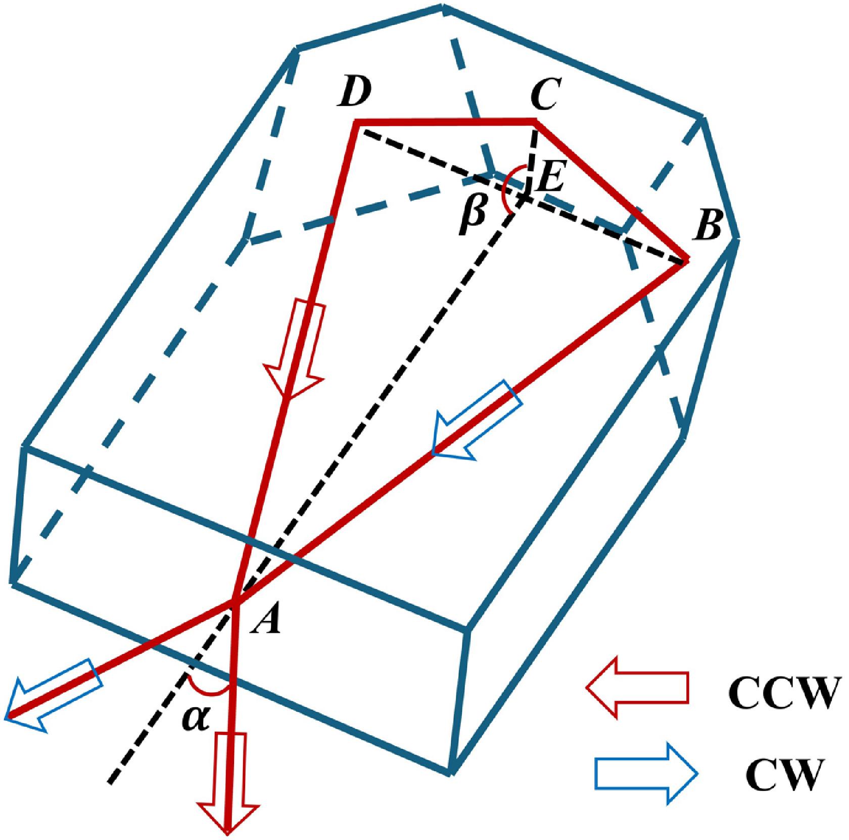
A typical geometry of monolithic NPRO [14] is shown in Fig. 1, where the nonplanar ring for laser oscillations is formed by quadrilateral . The blue and the red arrows represent the CW () and CCW () light paths, respectively. The equilateral triangles DAB and DCB have a dihedral angle of . And AE and CE are respective central lines (E is the midpoint of BD) in DAB and DCB. We use angle EAB (corresponding to exterior incident angle ), lengths AE and CE, and dihedral angle to define the geometry of ABCD and finally the NPRO. The NPRO is made of a gain medium, where surface A is coated for high transmittance (HT) at pump wavelength and high reflectance (HR) at signal wavelength. Planes B, C, and D are finely polished for total reflections.
Figure 1.A typical NPRO geometry and its internal light paths. , incident plane; , , , total reflection planes; , midpoint of ; , exterior incidence angle; , dihedral angle.
According to eigenpolarization theory [26], when a magnetic field is applied on NPRO, it may excite two polarization modes in each of the CW and CCW directions. Due to the different nonreciprocal rotations of the polarizations, the four modes have different losses. When the loss difference between the first two low-loss modes is higher than a certain value [27], unidirectional lasing is generated. When the loss difference is reduced by decreasing the applied magnetic intensity, bidirectional lasing is possible. However, due to the strong mode competition, this bidirectional lasing is usually unstable. Recently, we found that when the output laser is reinjected to NPRO under certain magnetic intensities, i.e., in a regime of laser feedback interferometry, stable bidirectional lasing in both the CW and CCW directions is generated [30]. Due to mode-coupling, the intensity in both directions can be expressed as (see Appendix A for details) Here, and are the CW and CCW laser intensities without feedback, and and are the laser intensities with feedback, respectively. is the corresponding excitation ratio for the two modes [33] (which, in our condition, is set equal for the two modes). is the reinjection rate which is related to the reflectivity of the feedback mirror. is the initial decay rate of the laser cavity when the magnetic field is zero. is the angular frequency difference between the two modes, which is mainly introduced by the magnetic field. is the laser angular frequency () used for feedback. is the photon time delay between the NPRO and the feedback mirror, which is considered to be constant during the gyroscope operation. From Eqs. (1) and (2), one can see that the laser intensities in both directions contain two terms: one is constant and the other represents a modulation with an angular frequency of . Thus, a beat frequency of will be detected in both directions without beam combination (combine CW and CCW light beams outside the resonator) as necessarily done in conventional RLGs. Moreover, benefiting from this nonzero beat frequency, the NPRO gyroscope will work on small angular velocities without a lock-in effect. When an angular velocity is added on the NPRO, the Sagnac effect induced frequency shift will be added on . Therefore, the angular velocity will be resolved by detecting the beat frequency shift.
The Sagnac effect induced frequency shift between the CW and CCW modes can be expressed as where is the vector area of the ring, is the vector angular velocity, is refractive index of the material, is the circumference of the ring, and is the wavelength of the laser [1]. Because the ring in this work is nonplanar, when the direction of the angular velocity is defined, the ring area could be replaced by a projection area along the direction of the angular velocity , i.e., . Here, we define the direction of the angular velocity as along the normal vector of the triangle DAB in this work.
Figure 2.(a) Schematic of the experimental setup for NPRO gyroscope. LD, laser diode; CM, collimator; DM, dichroic mirror; TEC, thermoelectric cooler; Att, optical attenuator; PD, photodetector. The current supply, temperature controllers, and electronics used for signal amplifying and filtering are not shown. (b) Spectrum of a typical beat signal at 346 kHz measured with resolution bandwidth (RBW) of 100 Hz.
In the experiment, the pump power is at 808 nm, and the output power is at 1064 nm in total. The total electric power consumption from the LD, TECs, and photodetector is less than 0.7 W at room temperature without considering the driving circuit efficiencies. The position of the magnet is scanned as done in Refs. [27,30] to find a good beat signal. Figure 2(b) shows a typical beat signal at 346 kHz after filtering and amplifying, where the corresponding magnetic intensity in the middle of NPRO is measured to be . When a stable beat signal is found, it means the NPRO gyroscope is in steady state and ready to operate.
3. NPRO GYROSCOPE MODE COMPETITION
Nd:YAG crystal is believed to be a homogeneously line-broadened gain medium. This will lead to mode competition between its CW and CCW laser modes in the ring cavity [22]. Even though Faraday rotation has split the CW and CCW laser frequencies in NPRO, the mode competition still exists. This is reflected in the frequency stability of the beat signal. In the experiment, we found that the beat frequency stabilities are quite different among different NPRO samples. We suspect this difference may come from the different lattice-defect effects in different NPRO samples. The lattice-defect induced inhomogeneous line-broadening in Nd:YAG crystal may weaken the mode competition, which in turn increases the beat frequency stability. For this reason, we design an experiment to examine the relation between the lattice defect and the mode competition. We will use wavefront distortion to indirectly display the lattice defects accumulated on the optical path in NPRO, and use the beat frequency noise to represent the level of mode competition.
Figure 3(a) shows the scheme to measure the wavefront distortion in NPRO. The commercial interferometer (InterFero, Hi-speed po) used here has a laser wavelength of 632.8 nm and optical aperture of 30 mm. It uses random phase-shifted interference between the transmitted beam and the reference beam (inside the instrument) to resolve the wavefront information of an objective. Because of the small cross-section of NPRO, an adjustable optical stop is used to filter the aperture to a suitable size. The position of the NPRO sample is finely adjusted to match its optical path to the 632.8 nm light. The transmitted 632.8 nm light after NPRO is reflected by a mirror back to the interferometer. In this way, the interference between the transmitted beam and the reference beam is constructed in the interferometer.
Figure 3.(a) Scheme of measuring wavefront distortion in NPRO; (b), (c) wavefront distortions measured with two different NPRO samples. The RMS and PV values are given.
Figures 3(b) and 3(c) show two typical measurement results corresponding to two NPRO samples, which have the same parameters on the datasheets. The RMS/PV (root mean square value/peak-valley value) of two samples are (former) and (latter). We have measured several samples and did find the NPRO distortion values are different from different samples. Subsequently, we use the above two samples to compare their beat frequency noises. The beat frequency noises calculated by amplitude spectrum density using data from the frequency counter are shown in Fig. 4. The high-distortion NPRO has lower beat frequency noise, which behaves as expected. Thus, it verifies that high-distortion NPRO will have lower mode competition. In the following experiments, the NPRO gyroscope will use the high-distortion NPRO sample if there is no further explanation.
Figure 4.Beat frequency noise comparison between beat signals from low-distortion (beat frequency at 328 kHz) and high-distortion (beat frequency at 334 kHz) NPRO samples.
Using parameters shown in Table 1 (column 2), we calculate the gyroscope parameters and to be and , respectively. Then we have the scale factor of from Eq. (3). To measure the scale factor, the rotating platform is set with different positive and negative rotating speeds. The corresponding frequency shifts of the beat frequency are recorded using the frequency counter. Figure 5 shows the beat frequency shifts (offset frequency at 334 kHz) with rotation speeds changed from to , where each point is averaged by five times. A linear fitting gives a slope of (with coefficient of determination of 0.9999), which is very close to the theoretical prediction. This illustrates that the NPRO gyroscope works in a very linear regime at low rotation speeds and has no noticeable lock-in effect.
Figure 5.NPRO gyroscope beat frequency shift with different rotational speeds. The offset frequency is at 334 kHz.
Figure 6 shows the Allan deviation curve using 30-minute data from the frequency counter when the NPRO gyroscope is in steady state. From Fig. 6, the NPRO gyroscope demonstrates an angle random walk (ARW) of and a bias instability (BI) of . The Allan deviation (if converted to the unit of hertz) is far lower than those shown in Ref. [29], where the twin-NPRO scheme is used to construct the gyroscope. We believe this significant improvement is attributed to the fact that the two beams share the same path in the single monolithic NPRO, where the correlated noises are common-mode rejected.
Figure 6.Allan deviation of the NPRO gyroscope beat frequency.
To investigate the limitation of the frequency stability, three factors are considered, including the pump power noise, the NPRO temperature noise, and the magnetic noise. We first measured the modulation coefficients from the pump power, the NPRO temperature, and the magnetic intensity to the beat frequency around their corresponding nominal values, which are respectively , , and (see Appendix B for details). Then we measured the pump power noise, the NPRO temperature noise, and the magnetic intensity noise. In the end, the corresponding noises are transferred to frequency noises with their modulation coefficients. The results are shown in Fig. 7, where the red, green, brown, and blue solid curves correspond to the beat frequency noise, the pump power noise, the NPRO temperature noise, and the magnetic noise, respectively. From Fig. 7, one can see that the NPRO temperature noise and the pump power noise are not the limiting factor. The main limiting factor is the magnetic noise. The magnetic noise curve is overlapped with the beat frequency noise below 0.03 Hz (Fourier frequency). And it is even higher than the latter from 0.03 Hz to 0.3 Hz. To investigate the reason, we measured the magnetic background noise by removing the magnet from the NPRO sample, which is shown by the gray solid curve in Fig. 7. By comparing the gray and the blue curves, one finds that the magnetic noise (with the magnet around the NPRO) is higher than the magnetic background noise (without the magnet around the NPRO) below 0.01 Hz. This proves the magnetic noise measurements are effective. The overlapping between the magnetic noise and the magnetic background noise above 0.01 Hz predicts that the magnetometer noise floor is reached. Further investigation reveals that opening the loop of the temperature controller for the NPRO sample will decrease the magnetic noise. This means the current noise in the TEC below the NPRO sample is coupled to the magnetic noise. It is also worth noting that the broad noise peak at around 40 Hz in the red curve might come from the vibration noise of our optical table [34].
Figure 7.Noise investigations for the NPRO gyroscope. Red: beat frequency noise of the NPRO gyroscope in steady state; blue: magnetic noise measured with magnet in nominal position around the NPRO; gray: magnetic background noise measured when the magnet is removed; brown: NPRO temperature noise; green: pump power noise.
5. NPRO GYROSCOPE PACKAGE DESIGN AND FUTURE IMPROVEMENTS
In order to have a good field application and noise isolation, a conceptual physical package for the NPRO gyroscope is designed as shown in Fig. 8(a). An aluminum alloy shell can package all the optics and basic electronics together, where laser diodes with lenses, NPRO sample, magnet, mirrors (including the dichroic mirror), thermistor, TEC, and photodetector with optical attenuator are assembled in a enclosure. Note that the TEC can also be mounted outside (below) the package and magnetic shielding material such as nanocrystalline alloy can be further used to shield the environmental magnetic field and weaken the noise coupling between the TEC current and the inside magnetic field (from the magnet). Moreover, this package will release the usage of moving mechanics and greatly decrease the optical path lengths. Thus, it will isolate parts of environmental temperature, and magnetic and vibrational noises. The total power consumption in the package is less than 0.7 W referenced to the demonstration experiment in Section 2 and can be further decreased with optimization in the future. The mass of the package is estimated to be less than 20 g.
Figure 8.(a) A conceptual package design of NPRO gyroscope with all optics and basic electronics. The body dimension of the package is . (b) A new NPRO design with top and left views. The gain medium is Nd-glass. The purple line is the optical path. The dimension is . (c) Projected bias instability versus scale factor (projected from Fig. 6). The black dashed line marks the Earth rotation speed; the blue and red points represent the bias instability achieved in the present experiment and the projected bias instability using the new NPRO sample under design, respectively.
Except for the package, there are a few strategies to further improve the NPRO gyroscope in the future. First, from the scale factor point of view, the NPRO samples used in the experiment are not specially designed for gyroscope applications. The small inner incident angle and big dihedral angle mean the projection area for rotating sensing is much smaller than the available area of the gain medium. Thus, a new NPRO sample is designed with parameters shown in Table 1 (column 3) and with geometry shown in Fig. 8(b). It is worth to mention that the refractive index is also a parameter that needs to be considered according to Eq. (3). Thus, a gain medium with a low refractive index is chosen to be Nd-glass. With these efforts, the scale factor can be increased significantly from 38.3 to with only a tiny dimension increasing. Figure 8(c) shows a bias instability curve projected from Fig. 6, where we assume the beat frequency stability is the same while the scale factor is changed. Apparently, the new NPRO sample will have a projected bias instability that is lower than the rate of Earth rotation (15 deg/h), which may be used for Earth rotation measurement in the future.
Second, from active noise suppression point of view, the NPRO gyroscopes also have a lot of room to gain stability. The magnetic noise is possible to be actively suppressed by using a small solenoid coil as the actuator and a magnetic sensor as the probe. The pump power noise can be suppressed by an active feedback loop. And the temperature noise can also be suppressed by passive isolation and by active second-order temperature controlling simultaneously. With all the above efforts, we believe the stability of the NPRO gyroscope can be improved at least one order of magnitude.
6. CONCLUSIONS
In summary, we have proposed and demonstrated, for the first time, a novel all-solid-state, miniature RLG based on a millimeter-sized, single monolithic NPRO. Its CW and CCW laser modes are passively stabilized under a regime of laser-feedback interferometry. Benefiting from the different frequency shifts of laser modes under a magnetic field, the NPRO gyroscope has a nonzero beat frequency in steady state, which makes it avoid a lock-in effect. The mode competition effect in NPRO gyroscopes is studied, which reveals that an NPRO sample with higher wavefront distortion will have a higher beat frequency stability. On that basis, we demonstrated that the NPRO gyroscope experimentally has a bias instability of and an angle random walk of under a scale factor of . And the instability is mainly caused by the magnetic noise at present. We further discussed the physical package design of the NPRO gyroscope, which has a dimension of , power consumption of less than 0.7 W, and mass of less than 20 g. A specially designed Nd-glass NPRO sample and active noise suppression with feedback loops will improve the NPRO gyroscope to have a bias instability of below the rate of Earth rotation. Benefiting from its compact size, rigid structure, low power consumption, and high stability, the NPRO gyroscope may find important applications in the field of inertial navigation, attitude control in aerospace, defense, and industry in the future.
Acknowledgment
Acknowledgment. The authors would like to thank Huizong Duan, Xiaopeng Xie, and Yizhong Huang for helpful discussions.
APPENDIX A
To derive Eqs. (1) and (2), we start from two-frequency laser rate equations [33,35] combined with the Lang-Kobayashi equation [36]. The Nd:YAG four-level system can be simplified to a two-level system. The complex forms of the two-frequency laser equations are given as follows [30]:where we consider the case when the reinjected light is from the CCW laser mode. and are defined in Section 2. and represent the complex amplitude of the two electric fields. is the population inversion decay rate, which is assumed to be identical for both laser modes because of the same population inversion they are sharing. and are the decay rate of the laser cavity in CW and CCW modes, which are assumed to be different because of the nonreciprocity of NPRO [26]. is the excited emission coefficient, which is related to the Einstein coefficient . To describe the coupling between the CW and CCW modes, coefficients and are introduced as the ratio of the cross- to the self-saturation coefficient, and represents the nonlinear coupling constant [32]. and are the unsaturated population inversion of the CW and CCW modes, respectively. and represent population inversion of CW and CCW modes, respectively. and are defined as before.
In the NPRO system, the CW and CCW laser modes come from the same population inversion, so we define the total unsaturated population inversion of NPRO as the sum of two directions, . And we define and , which are the corresponding excitation ratios for the two modes [34], where and are the stationary population inversions without optical feedback. Since these bidirectional laser modes come from the same energy level transition and share the total unsaturated population inversion , the two excitation ratios are the same, which means . Then we get the relation between two unsaturated population inversions:We then define and and are the stationary optical intensities of the CW and CCW laser modes without optical feedback:
With optical feedback, the stationary intensity solutions are solved from Eqs. (A1)–(A4) as where .
APPENDIX B
The modulation coefficients are measured as follows. The pump power at 808 nm is measured after the lens under different pump currents. The temperature around the NPRO is measured by an individual thermistor that is connected to a multimeter (Keysight, 34465A). The temperature around the NPRO is changed by setting the temperature controller (Analog Technologies, TECEV104). The magnetic field is measured at the center of the NPRO sample (it is removed when measuring the magnetic field) by a magnetometer (COLIY, G401). The magnetic intensity is changed by changing the position of the magnet. All the parameters are tuned around their nominal values, i.e., the pump power is in the range of 100–106 mW, the temperature is within 25°C–26°C, and the magnetic intensity is in the range of 21–31 mT. The beat frequency change is recorded by the spectrum analyzer. Figures 9(a)–9(c) show the measurement results corresponding to the pump power, the NPRO temperature, and the magnetic intensity, respectively. Linear fitting gives three modulation coefficients of , , and , respectively.
Figure 9.Modulation coefficient measurement results. (a) Beat frequency versus pump power; (b) beat frequency versus NPRO temperature; (c) beat frequency versus magnetic intensity. Red squares: measurements; black solid lines: linear fitting. The slopes and coefficients of determination are given.
[6] Y. Y. Broslavets, D. M. Ambartsumyan, V. G. Semenov. Multifrequency solid-state ring laser gyroscope based on YAG:Cr4+. 28th Saint Petersburg International Conference on Integrated Navigation Systems (ICINS), 1-8(2021).
 AI Video Guide
  AI Picture Guide
 AI One Sentence