1Shandong Provincial Engineering and Technical Center of Light Manipulations & Shandong Provincial Key Laboratory of Optics and Photonic Device, School of Physics and Electronics, Shandong Normal University, Jinan 250014, China
2Collaborative Innovation Center of Light Manipulation and Applications, Shandong Normal University, Jinan 250358, China
3Joint Research Center of Light Manipulation Science and Photonic Integrated Chip of East China Normal University and Shandong Normal University, East China Normal University, Shanghai 200241, China
【AIGC One Sentence Reading】:We propose a microsphere-assisted method for single-shot, high-resolution quantitative birefringence imaging of dynamic samples using polarization holographic microscopy.
【AIGC Short Abstract】:We propose a microsphere-assisted single-shot polarization holographic microscopy method for high-resolution quantitative birefringence imaging. Our system and algorithm enable simultaneous imaging and measurement of 2D birefringence in dynamic samples, with resolution beyond the limit of conventional microscopy, as demonstrated by imaging a resolution target and a rotating grating.
Note: This section is automatically generated by AI . The website and platform operators shall not be liable for any commercial or legal consequences arising from your use of AI generated content on this website. Please be aware of this.
Abstract
We propose a method for realizing single-shot high-resolved quantitative birefringence microscopy by extending microsphere-assisted microscopy into polarization holographic microscopy. Based on our proposed imaging system and reconstruction algorithm, we are capable of simultaneously realizing high-resolved polarization holographic imaging and quantitative measurement of 2D birefringence information of dynamic samples. We demonstrated our proposed method by quantitatively imaging a birefringence resolution target, whose resolution (0.71 µm) exceeds the resolution limit of a microscope objective with a numerical aperture of 0.25. Experimental results of rotating holographic diffraction grating with 500 lp/mm further demonstrated the feasibility of our method in birefringence imaging of dynamic samples.
Polarization microscopy has unique features for nondestructive real-time imaging and measuring the heterogeneous specimens that are visible primarily due to their optically anisotropic characteristics, such as dichroism and birefringence. Birefringence characterizes the refractive index anisotropy, which mainly arises from the ordered arrangement of the microscopic structures in anisotropic materials such as tissues[1,2]. Birefringence microscopy (BM) can achieve high-throughput optical imaging of an anisotropic sample without potentially harmful staining or labeling procedures and is therefore widely used in biomedicine[3–6]. For example, quantitative BM provides a powerful approach for histopathological assessment of myelin structural breakdown associated with many neurodegenerative diseases[3]. Additionally, extending BM to optical coherence tomography (OCT) enables non-invasive assessment of the progression of myopia and the organization of myelin[5,6].
Over the past decade, many related polarization microscopy techniques for measurement of the 2D birefringence parameter distributions of anisotropic samples have been successfully developed[7–13]. In our previous work[13], we proposed a quantitative polarization interference microscope slide that integrated with a commercial microfluidic chip. Although this scheme realizes polarized light microscopy imaging of birefringence information of a dynamic sample, it also has some inherent disadvantages associated with the experimental setup. For example, similar to other birefringence imaging methods[7–12], the lateral resolution of the imaging system cannot be enhanced to an unlimited level and is confined by Abbe’s law, which depends on the illumination wavelength and the effective numerical aperture (NA) of the optical system. On the other hand, the polarization aberration introduced by the high-NA lens, including diattenuation, depolarization, and linear retardance, will cause degradation of the polarimetric image, which has a negative impact on mapping the birefringence distribution of anisotropic materials[14]. How to obtain a high lateral resolution polarimetric image with low NA microscope objectives (MOs) is still a thorny question up until now.
Microsphere (MS) -assisted microscopy provides an effective and simple method to further enhance the resolution of microscopes[15–23]. In this scheme, an MS is typically placed between the sample and the MO to collect the diffracted light at larger angles, thus enhancing the resolution of the imaging system. In the last few years, MS-assisted microscopy has been extended into several microscopic techniques, including dark-field microscopy[24], atomic force microscopy[25], and holography microscopy[26]. Additionally, polarization microscopy also suffers from the diffraction-limited resolution issue. More recently, Abbasian et al.[27] achieved super-resolved polarimetric imaging of anisotropic materials by combining MS-assisted microscopy with Mueller matrix microscopy. In this framework, 36 intensity images captured by rotating the polarizers and retarders are required to obtain the 16 Mueller matrix elements. However, its applicability is limited to static specimens due to the necessity of the time-consuming scanning mechanism. Until now, no other MS-assisted polarized light microscopy has been proposed, especially any that is suitable for the polarization imaging of dynamic anisotropic samples.
Sign up for Chinese Optics Letters TOC. Get the latest issue of Chinese Optics Letters delivered right to you!Sign up now
Here, we propose an MS-assisted single-shot quantitative birefringence microscope (MS-SSQBM) that can realize quantitative birefringence imaging of dynamic anisotropic samples by combining MS-assisted microscopy with polarization holographic microscopy. Based on our proposed MS-assisted experimental system and retrieved algorithm, the holographic images associated with two polarization states as well as the 2D birefringence parameter distributions, all with an enhancing resolution, of a dynamic anisotropic sample can be simultaneously recovered from an angular-multiplexing hologram captured in one exposure.
2. Design Principle
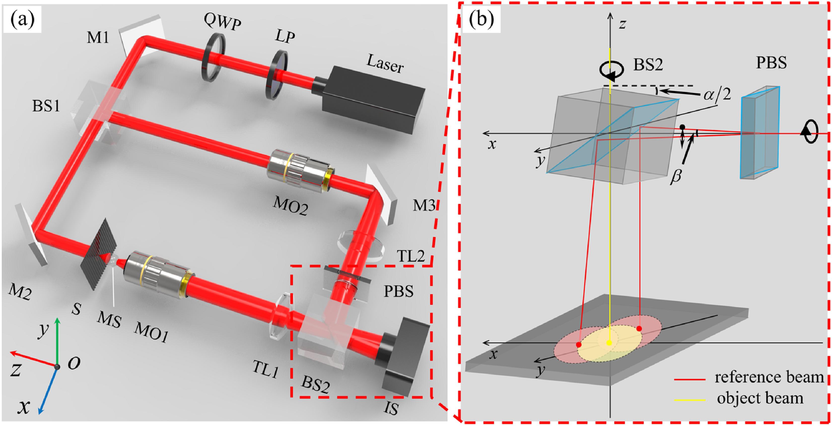
Figure 1 shows the schematic of our proposed MS-SSQBM for high-resolved quantitatively birefringence imaging of anisotropic materials. Essentially, it is an MS-assisted Mach–Zehnder interferometer for realizing double-channel angular-multiplexing polarization hologram (AMPH) recording. In this system, the input beam emitted from a laser is converted into a left-handed circular-polarization state by a linear polarizer (LP) and a zero-order quarter-wave plate (QWP), and then the circular-polarization beam is divided by a non-polarizing beam splitter (BS1) into two beams: the illumination beam and the reference beam, respectively, incident in the object arm and reference arm of the interferometer. In the object beam arm, an MS, a microscope objective (MO1), and a tube lens (TL1) are sequentially inserted. The MS is placed over the anisotropic sample (S) and within the working distance of the MO1, which is used to realize resolution improvement of the system. The transmitted beam of the sample (S) sequentially passes through the MS and a magnification system, consisting of the MO1 and the TL1, and reaches the recording plane of the image sensor (IS) located at the imaging plane of the object. It should be noted that adding an MS to a traditional microscopic system will inevitably introduce spherical aberrations and curved deformation into the measured results. Fortunately, any aberrations and distortion of the reconstructed images can be eliminated in digital holography simply by taking a background hologram captured in the same configuration without the sample. In the reference beam arm, the reference beam passes through a magnification system composed of MO2 and TL2 and is incident onto a polarization beam splitter (PBS), which is inserted just before the non-polarizing beam splitter (BS2). The transmitted beam is divided into two reference beams with orthogonal polarization states, each of which has a different propagation direction. By choosing a suitable reflection angle of the BS2, these three beams can be superimposed on the IS and form an AMPH with approximate orthogonal interference fringes.
Figure 1.(a) Schematic of the microsphere-assisted high-resolved quantitative birefringence microscopy setup. (b) The detailed description of the beam propagation paths and arrangement of the optical components in the red box of (a).
For a birefringence sample, its birefringence can be characterized quantitatively by the parameters of the optic-axis orientation and the birefringence phase retardation , where is the thickness of the anisotropic sample, is the wavelength of the incident laser beam, and and are the refractive indices of the birefringence sample for incident polarization states, respectively, parallel and vertical to the optic axis. Birefringence of the sample is also often characterized quantitatively by the Jones matrix , and the relationship between the Jones matrix and the birefringence parameter ( and ) can be written as where represents the absorption coefficient of the birefringence sample. When the sample is illuminated by a left-handed circular-polarization beam, the transmitted field of the sample sequentially passes through an MS placed over the sample and a magnification system, consisting of an MO1 and a TL1, and reaches the imaging plane. It should be mentioned that an MS placed over the sample is used to increase the effective NA of the system, allowing the collection of light at larger diffracted angles, thus improving the resolution of the system. The Jones vector of the transmitted field at the recording plane can be expressed as where represents the intensity of the illuminating beam, and denotes the spherical aberrations and curved deformation caused by an MS of non-polarizing material. Substituting Eq. (1) into Eq. (2) and after some mathematical operations, Eq. (2) can be further simplified as
In the reference arm, the reference beam sequentially passes through MO2 and TL2 and is incident onto a Wollaston prism (WP) with an azimuth angle of 90° [as shown in Fig. 1(b)] and is divided into two beams with both orthogonal polarization states and different propagation directions. Furthermore, the two reference beams are reflected by BS2, with a rotation angle , and reach the recording plane. The propagation path of the beam and the description of the arrangement of the optical components are shown in detail in Fig. 1(b). The two reference beams on the IS plane can be also expressed using a Jones vector, as follows: where and are the constants, and is determined by the PBS. The reference Jones vector given by Eq. (4) and the image Jones vector given by Eq. (3) interfere with each other at the recording plane, as shown in Fig. 1(b), and form the so-called AMPH. The recorded total intensity of this AMPH can be expressed as
From Eqs. (3) and (5), it can be seen that the birefringence phase retardance and the optic-axis orientation angle are among the terms and , which can be directly extracted from the AMPH using a conventional spatial filtering algorithm[28,29] in the reconstruction process of such an angular-multiplexing off-axis hologram. If the two-channel angular-multiplexing off-axis holographic recording system is designed correctly, the optimized space bandwidth is utilized to record the whole information of the wavefield[30], ensuring that the two wavefronts encoded may be fully reconstructed without loss of resolution or field of view (FOV)[31]. Furthermore, the spherical aberrations and curved deformations caused by the MS and the undesired coefficients can be eliminated using the following formula: where and correspond to the reconstructed values from one background AMPH, which can be captured by the same experimental setup in the absence of the tested sample. To find the birefringence parameters of an anisotropic sample from the reconstructed and , we can calculate the quantity ,
From Eq. (7), it can be seen that the module of is related to the tangent of half of the birefringence phase retardation, while its argument is equal to two times the optic-axis orientation angle.
3. Experimental Setup and Results
Figure 2(a) shows the real experimental setup for recording the AMPH constructed based on the schematic illustrated in Fig. 1(a). In this system, a He-Ne laser is used as the light source, which is not shown in Fig. 2(a). The laser first passes through a spatial filter (SF) with a pinhole of 15 µm and then is collimated by a collimating lens (CL) with . Furthermore, the collimated beam is converted into a left-handed circular-polarization beam by an LP and a zero-order QWP. MO1 and MO2 are with the same optical parameters (, 0.25 NA), and TL1 as well as TL2 has the same focal length of 200 mm. In the object arm, a silica MS (Edmund Optics, ) with a diameter of 500 µm is inserted and mounted at the end of an optical fiber holder, whose position can be flexibly adjusted using translation stages. The sample is fixed on a motorized rotation stage (MRS) and is further magnified by an MS-assisted imaging system, whose magnification factor is determined by the magnification of the system and the additional magnification factor of MS. In the reference beam path, a Wollaston prism with a splitting angle of 3 deg is employed as the PBS for generating two orthogonal polarization reference beams. The parameter is also adjusted to be approximately equal to 1.5 deg by adjusting the angle of the BS2, ensuring that the interference fringes of the AMPH are orthogonal. In the experiment and for simplicity, the angle should be adjusted first and then inserted into the wave plate with the azimuth angle of 90° (along the -axis) in the reference arm, as shown in Fig. 1(b). A global shutter CMOS camera with a pixel number of and a pixel pitch of 3.45 µm was used to capture the AMPH. Figure 2(b) presents a part of one AMPH recorded in our experimental system without the sample. Figure 2(c) is the spatial spectrum of the AMPH obtained by performing a 2D Fourier transformation operation on Fig. 2(b), where the frequency components corresponding to the terms and in Eq. (6) are indicated by two red-dotted circles.
Figure 2.(a) Experimental setup of the system constructed based on Fig. 1(a). (b) Example of the AMPH captured by the experimental setup of (a). (c) Fourier spectrum of the AMPH.
In order to demonstrate the polarization imaging performance of our proposed MS-SSQBM system, a calibrated 632.8 nm QWP was chosen as the first tested sample. Figure 3 shows the polarization images of the background and the QWP with a rotation angle of 100 deg from the -axis. Figures 3(a1) and 3(b1) are the amplitude distributions associated with two orthogonal polarization states reconstructed from one background AMPH captured by our experimental setup without the sample, while Figs. 3(c1) and 3(d1) are the corresponding phase distributions. From Figs. 3(c1) and 3(d1), the same spherical phase deformations are observed in the phase distributions of the two polarization states. Figures 3(e1) and 3(f1) are the birefringence phase retardation and optic-axis orientation distributions retrieved from the above reconstructed complex amplitude distributions, respectively. As shown in Fig. 3(e1), the birefringence phase retardation caused by the MS is nearly close to 0, indicating that the MS is isotropic. Figures 3(a2), 3(b2), 3(c2), and 3(d2) present the reconstructed amplitude and phase distributions of the QWP, associated with two polarization states, from only one AMPH captured by our experimental setup, respectively. Similar spherical phase deformations (except for the absolute phase distributions) also appear in both orthogonal polarization components, as shown in Figs. 3(c2) and 3(d2).
Figure 3.Example of the measured birefringence phase retardation and optic-axis orientation maps of the QWP without and with the MS in our MS-SSQBM system. (a), (b) The recovered amplitude distributions associated with two polarization states of the background and sample. (c), (d) The recovered phase distributions associated with two polarization states of the background and sample. (e), (f) The retrieved birefringence phase retardation and optic-axis orientation distributions of the background and sample images, respectively. Scale bar: 20 µm.
From Figs. 3(e2) and 3(f2), it can be seen that both the birefringence phase retardation and optic-axis orientation distributions, respectively, retrieved from Figs. 3(a2), 3(b2), 3(c2), and 3(d2), are almost uniform, without significant spherical deformation. To eliminate the undesired deformation, the complex amplitude distributions of the QWP associated with two polarization states, shown in Figs. 3(a3), 3(b3), 3(c3), and 3(d3), were reconstructed using Eq. (6), which are almost consistent with the complex distributions [shown in Figs. 3(a4), 3(b4), 3(c4), and 3(d4)] reconstructed from an AMPH recorded in the experiments without an MS insertion. Further, the birefringence phase retardation and optic-axis orientation distributions of the QWP were also reconstructed using Eq. (7), which is also in agreement with retrieved results in the experiments without an MS, as presented in Figs. 3(e4) and 3(f4), respectively.
Figure 4.Combination of the measured birefringence information curves of the QWP without and with the insertion of the MS in the setup for rotation angles of 0 rad to π rad.
The above experimental results demonstrate that the spherical deformation caused by the MS can be effectively removed by our proposed algorithm. From the measured birefringence images shown in Fig. 3, their noise is relatively high. To evaluate the quality of the reproduced image, the peak signal-to-noise ratio (PSNR) of the reconstructed birefringence images has been calculated. The PSNR of the retrieved birefringence phase retardation and optic-axis orientation without MS are 12.3 and 14.2, respectively, while the PSNR of the retrieved birefringence phase retardation and optic-axis orientation with MS are 11.9 and 13.8, respectively. This means that the insertion of the MS into the system did not introduce additional noise. The noise is mainly caused by the shot noise and time stability of the IS because an 8-bit industrial camera is used to record the hologram. The quality of the reconstructed birefringence images can be improved using a scientific complementary metal-oxide semiconductor (sCMOS) camera to record the hologram.
To further validate the quantitative imaging ability for the birefringence parameters of our proposed MS-SSQBM system, the birefringence phase retardation and optic-axis orientation of the QWP without and with an MS were, respectively, measured and shown in Fig. 4, when it is rotated from 0 to rad with increment. In Fig. 4, the retrieved average retardance without and with an MS as a function of the rotation angle is plotted in red circles and black squares, and the actual retardance is also plotted in a purple dashed line. The mean of the measured phase retardance of the QWP with an MS is determined to be rad, which is in good agreement with the actual retardance of . The recovered optic-axis orientation without (in blue triangles) and with an MS (in green triangles) and the actual optic-axis orientation (in an orange dashed line) as a function of the rotation angle are also presented in Fig. 4. The experimental results of Fig. 4 show that the measured phase retardation and axis orientation of the QWP without and with an MS are almost consistent with the actual values. The measurement sensitivity of the birefringence phase retardation and optic-axis orientation of the system are also estimated as 0.03 and 0.02 rad, respectively.
Next, we performed imaging of a birefringence resolution test target to further investigate the birefringence imaging resolution of our MS-SSQBM. Figure 5 shows an example of the experimental results, in which the birefringence parameters retrieved with the setup without the MS insertion are also presented for comparison. Figures 5(a1) and 5(b1) are the recovered amplitude distributions of two polarization components of the tested resolution target without the MS insertion, while Figs. 5(a2) and 5(b2) present the corresponding amplitude distributions with insertion of the MS. From Figs. 5(a1) and 5(b1), it can be seen that the line pattern with 300 lp/mm in horizontal and vertical alignment with a line width of 1.66 µm of the tested resolution target can be distinguished in the birefringence microscopy setup without the MS. The line pattern with 330 lp/mm (1.52 µm line width) of the tested resolution target is relatively clear, while the line pattern with 360 lp/mm is blurry, since the spatial resolution of the objectives with is only 1.54 µm. The retrieved amplitude distributions in Figs. 5(a2) and 5(b2) clearly show the distinguishability of the line pattern with 700 lp/mm (833 nm line width) of the tested resolution target in the MS-SSQBM. But the line pattern with 850 lp/mm is very blurry. A similar experimental performance has also been observed in the retrieved phase distributions of the tested resolution target, as shown in Figs. 5c(1), 5c(2), 5d(1), and 5d(2).
Figure 5.Example of holographic birefringence imaging of a birefringence resolution target without and with the insertion of an MS in the setup. (a), (b) The recovered amplitude distributions of two orthogonal polarization states of the tested resolution target without and with an MS, respectively. (c), (d) The corresponding phase distributions. (e), (f) The recovered birefringence phase retardation and optic-axis orientation distributions without and with an MS, respectively. Scale bar: 4 µm.
Figures 5(e1) and 5(f1) are the retrieved birefringence phase retardation and optic-axis orientation distributions of the tested resolution target without an MS, and Figs. 5(e2) and 5(f2) present the corresponding birefringence information distributions with an MS. It shows that the reconstructed birefringence phase retardation and optic-axis orientation distributions of the line pattern of 300 lp/mm without an MS and the line pattern of 700 lp/mm with an MS are clear, and the corresponding mean of the measured phase retardance and optic-axis orientation are , and , , respectively, which agrees with the theoretical value of the birefringence resolution test target (, ). These experimental results demonstrate that the MS-SSQBM system can achieve a higher resolution than that of the conventional SSQBM system, for which the enhancement factor is about 2.33.
Lastly, a rotating holographic grating (500 lp/mm, Edmund Optics, 54-510) was chosen as a dynamic specimen to demonstrate the feasibility of our proposed MS-SSQBM system in quantitatively imaging the 2D birefringence information of a dynamic anisotropic object in a more general situation. The holographic grating is made from a clear polyester film of 76.2 µm thickness, which the birefringent effect mainly introduced by the polyester material[32], and its birefringent effect has also been observed in Ref. [27]. We conducted multi-frame shots of a rotating holographic grating with the speed of 30 r/min and produced a video streaming of the frame rates of 36 frame/s with these reconstructed birefringence images (see Visualization 1). It should be noted that the imaging speed of our system is mainly determined by the maximum frame rate of IS. A typical frame of the measurement results is shown in Fig. 6, and the birefringence parameters obtained in the setup without the MS insertion are also presented in Fig. 6, as a comparison.
Figure 6.Example of the holographic birefringence imaging of a 500 lp/mm holographic grating without and with the insertion of an MS in the setup. (a), (b) The recovered amplitude distributions of two orthogonal polarization states of the grating without and with an MS, respectively. (c), (d) The corresponding phase distributions. (e), (f) The recovered birefringence phase retardation and optic-axis orientation distributions without and with an MS, respectively. (g) The line profiles indicated by the dashed lines in (a). Scale bar: 10 µm.
Figures 6(a1) and 6(b1) give the recovered amplitude distributions of two polarization components of the holographic grating without the MS insertion, while Figs. 6(a2) and 6(b2) present the corresponding amplitude distributions with insertion of the MS. From Figs. 6(a1) and 6(b1), it can be seen that the recovered amplitude distributions of the two polarization components of the holographic grating cannot be distinguished in the birefringence microscopy setup without the MS. The retrieved amplitude distributions of Figs. 6(a2) and 6(b2) clearly show the distinguishability of the holographic grating structure in the MS-SSQBM. The same phenomenon is also observed in the phase distributions, as shown in Figs. 6(c) and 6(d). The period of the holographic grating is 2 µm, which causes a diffraction angle of 18.45° for . Since the acceptance angle of the objectives with an is only 14.48°, the retrieved amplitude and phase distributions of the holographic grating are indistinguishable in the conventional SSQBM system. Figures 6(e1) and 6(f1) are the retrieved birefringence phase retardation and optic-axis orientation distributions of the holographic grating without the MS, while Figs. 6(e2) and 6(f2) present the corresponding birefringence information distributions with the MS. The normalized intensity of the line profiles indicated by the dashed line in Figs. 6(a) is also given in Fig. 6(g), which shows that the MS-SSQBM can provide a relatively high contrast ratio. These experimental results demonstrate that the MS-SSQBM system can achieve a higher resolution than that of the conventional SSQBM system.
4. Conclusions
In conclusion, we have proposed an MS-assisted single-shot quantitative birefringence microscopic imaging method and system. In this system, a high-resolved recording setup can be built simply by inserting an MS in a conventional quantitative birefringence microscope. Based on the MS-SSQBM combined with our proposed algorithm, we simultaneously realized high-resolved birefringence imaging of a rotating holographic grating with a magnification factor of 27.7. The FOV of our proposed system is about , which is smaller than that of a 10× MO. Although the FOV of our proposed system is smaller than that of a high-NA MO, it can avoid polarization aberrations introduced by a high-NA MO[14], including diattenuation, depolarization, and linear retardance, which have a negative impact on mapping the birefringence distribution of anisotropic materials. Hence, our MS-assisted microscopic system without polarization aberrations is beneficial for accessing birefringence information of anisotropic samples. In addition, our work provides a low-cost and efficient approach for converting a conventional polarization imaging system into a microsphere-assisted high-resolved one. Most importantly, it is suitable for dynamic anisotropic samples. We believe that our method could play a positive role in realizing high-resolved imaging polarization phenomena in ultrafast and micro-nano fabrication processes[29,33,34].
 AI Video Guide
  AI Picture Guide
 AI One Sentence