
Ran Tao, Jifang Qiu, Yuchen Chen, Yan Li, Hongxiang Guo, Jian Wu, "A parameter-space-reduction-technique-assisted optimization method for characterizing recirculating waveguide meshes," Chin. Opt. Lett. 23, 021301 (2025)
- Chinese Optics Letters
- Vol. 23, Issue 2, 021301 (2025)
![(a) Feedforward-only waveguide mesh. (b) Recirculating waveguide mesh. (c) TBU within the feedforward-only waveguide mesh, typically implemented with an asymmetric MZI, featuring an internal PS on one arm and an external PS and two 50:50 BSs[2,3]. (d) The flexibility demanded by recirculating waveguide meshes necessitates a more compact TBU structure, typically implemented with a symmetric MZI, featuring PSs on both arms to allow dual-drive[3,22] and two 50:50 BSs. (e) User-defined functionalities are translated by the configuration algorithms to voltages applied to TBUs, achieving the so-called programming[7].](/richHtml/col/2025/23/2/021301/img_001.jpg)
Fig. 1. (a) Feedforward-only waveguide mesh. (b) Recirculating waveguide mesh. (c) TBU within the feedforward-only waveguide mesh, typically implemented with an asymmetric MZI, featuring an internal PS on one arm and an external PS and two 50:50 BSs[2,3]. (d) The flexibility demanded by recirculating waveguide meshes necessitates a more compact TBU structure, typically implemented with a symmetric MZI, featuring PSs on both arms to allow dual-drive[3,22] and two 50:50 BSs. (e) User-defined functionalities are translated by the configuration algorithms to voltages applied to TBUs, achieving the so-called programming[7].
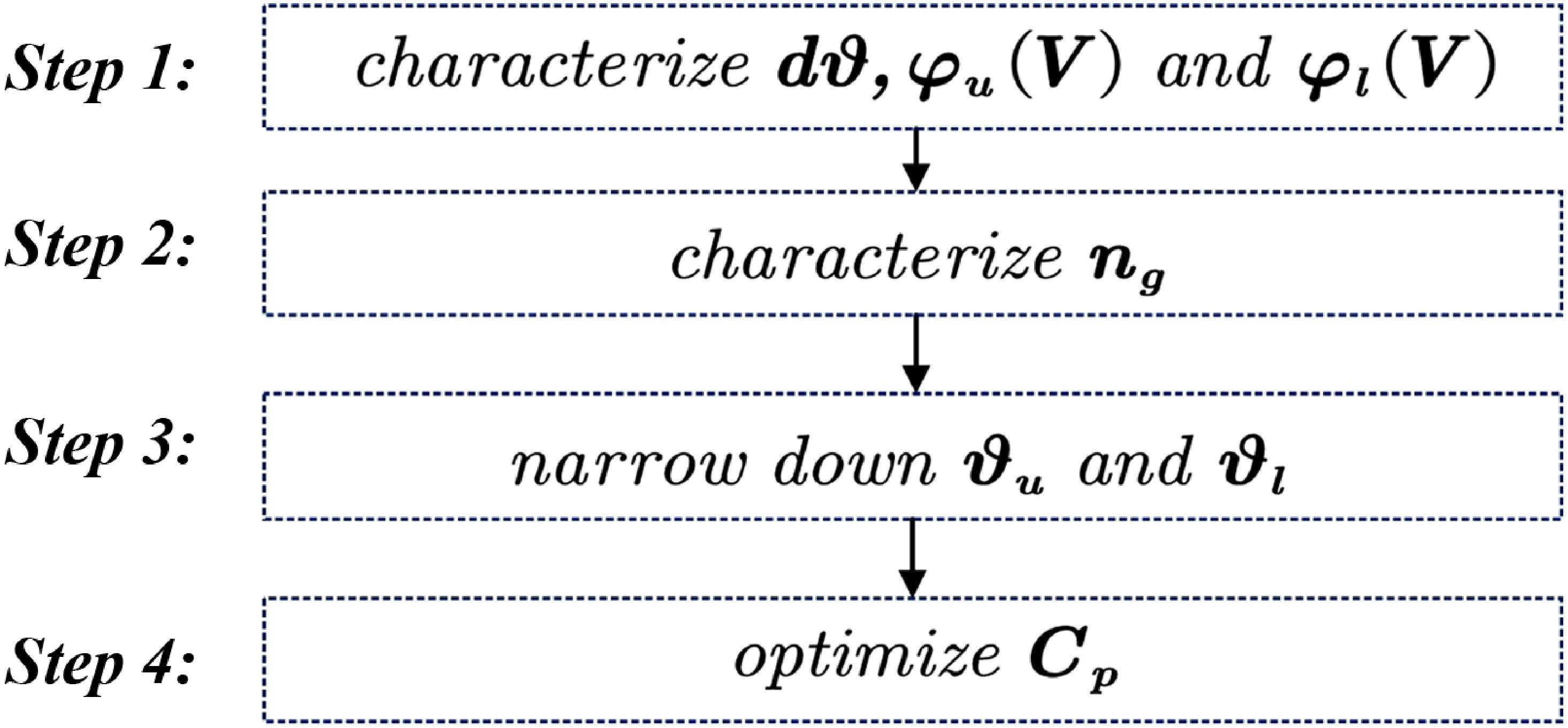
Fig. 2. Characterization procedure involving 4 steps. Step 1: characterize passive phase difference Cp with reduced parameter space.
Fig. 3. PDFs, along with error ranges and corresponding confidence levels of KBS and dϑ characterization errors and transmission matrix T prediction error.
Fig. 4. FIR applications. Circuit layout diagrams and waveguide mesh arrangements for three different FIR applications. (a), (b) MZIs with different arm length differences. (c) A 3-tap MZI lattice filter. (d), (e), (f) Spectral responses of the ideal, actual, and characterized meshes, when configured with voltages chosen based on ideal assumption, respectively, for the three applications. (g), (h), (i) Spectral responses of the actual and characterized meshes, when configured with voltages chosen based on the characterized


Set citation alerts for the article
Please enter your email address

© Copyright 2018-2021 | Chinese Laser Press. All Rights Reserved 沪ICP备15018463号-20