YUAN Lichao1,2,3,*, TAN Fengfu1,3, HUANG Zhigang1,3, CHENG Yilun1,2,3, and HOU Zaihong1,3
Author Affiliations
1Key Laboratory of Atmospheric Optics, Anhui Institute of Optics and Fine Mechanics, HFIPS,Chinese Academy of Sciences, Hefei 230031, China2University of Science and Technology of China, Hefei 230026, China3Advanced Laser Technology Laboratory of Anhui Province, Hefei 230037, Chinashow less
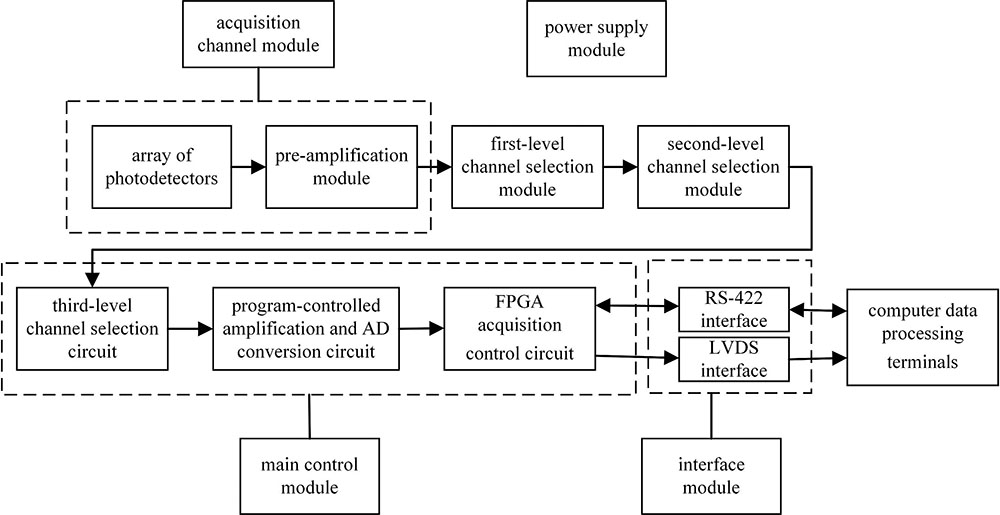
Fig. 1. Block diagram of the circuit system structure
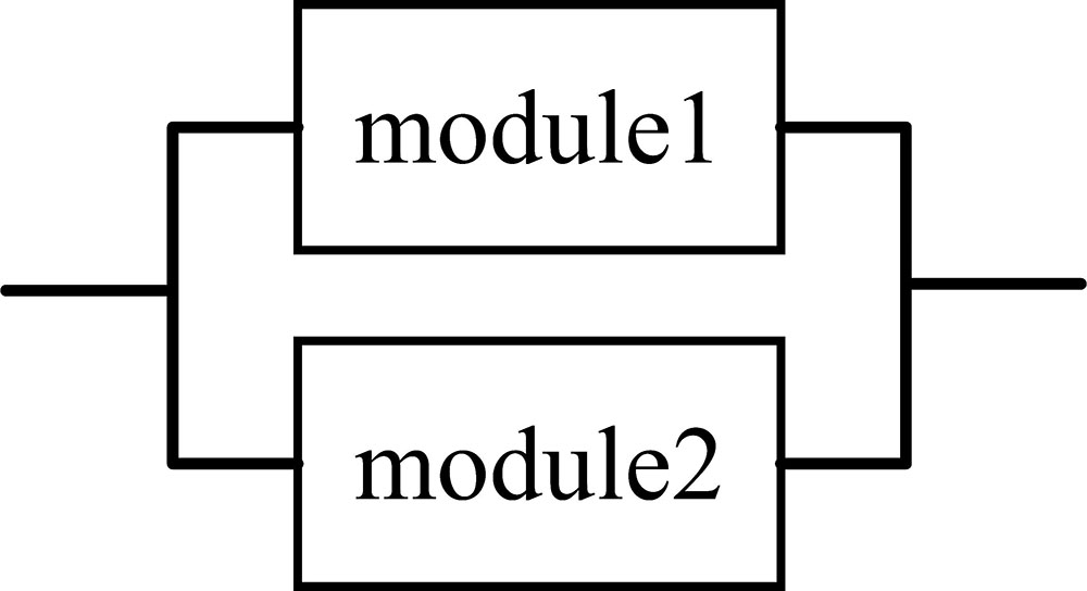
Fig. 2. Logical block diagram of parallel redundancy reliability
Fig. 3. Logical block diagram of reliability after redundancy
Fig. 4. Reliability logic block diagram after redundant design of the circuit system
| Category | Impact and consequence of failure |
|---|
| Ⅰ(Catastrophic) | Catastrophic failure that leads to the destruction of missile, satellite, rocket, spacecraft, or casualty | | Ⅱ(Lethal) | Critical failure that results in a critical loss of system functionality and task failure | | Ⅲ(Critical) | Critical failure that results in a mild loss of system functionality and task delay | | Ⅳ(Minor) | Minor failure that is not sufficient to cause loss of system functionality, but results in reduced system performance andrequires unplanned repairs |
|
Table 1. Severity classification
| Grade | Definition | Probability of failure |
|---|
| A | Often happen | The probability of a module failure is greater than 20% of the total failure probability of the array target circuit system | | B | Sometimes happen | The probability of a module failure is greater than 10% and less than 20% of the total failure probability of the array target circuit | | C | Occasionally happen | The probability of a module failure is greater than 1% and less than 10% of the total failure probability of the array target circuit | | D | Rarely happen | The probability of a module failure is greater than 0.1% and less than 1% of the total failure probability of the array target circuit | | E | Very rarely happen | The probability of a module failure is less than 0.1% of the total failure probability of the array target circuit |
|
Table 2. Table of fault occurrence level
| Name of the failure | Primary failure mode | Impact of failure | Severityclassification | Probability level of failure |
|---|
| Failure of the acquisition channel module | Photodetector failure, amplifier failure, resistance and capacitor failure | The corresponding acquisition channel has no output or outputdistortion | Ⅳ | A | | Failure of the first-level channel selection module | First-level channel selection switch failure, resistance and capacitor failure | The corresponding acquisition channel has no output or outputdistortion | Ⅳ | C | | Failure of the second-level channel selection module | Second-level channel selection switch failure, resistance and capacitor failure | The corresponding acquisition channel has no output or outputdistortion | Ⅲ | D | | Failure of the main control module | Device failure such as FPGA and AD converter | The system does not work properly and the task fails | Ⅱ | C | | Failure of the power supply module | Device failure such as filter and regulator | The system does not work properly and the task fails | Ⅱ | C | | Failure of the interface module | LVDS driver, RS-422 driver and other device failure | The system does not work properly and the task fails | Ⅱ | B |
|
Table 3. Array target circuit system module failure analysis table
| Module name | Importance |
|---|
| Acquisition channel module | 0.002 | | First-level channel selection module | 0.033 | | Second-level channel selection module | 0.500 | | Main control module | 1.000 | | Power supply module | 1.000 | | Interface module | 1.000 |
|
Table 4. Importance of each module
| Module name | Complexity |
|---|
| Acquisition channel module | 0.8787 | | First-level channel selection module | 0.0982 | | Second-level channel selection module | 0.0064 | | Main control module | 0.0102 | | Power supply module | 0.0034 | | Interface module | 0.0031 | | Total | 1.0000 |
|
Table 5. Complexity of each module
| The name of the failure | Failure rate/h |
|---|
| Failure of the acquisition channel module | 9.33×10⁻⁴ | | Failure of the first-level channel selection module | 7.03×10⁻⁵ | | Failure of the second-level channel selection module | 4.58×10⁻⁶ | | Failure of the main control module | 1.11×10⁻⁵ | | Failure of the power supply module | 6.49×10⁻⁶ | | Failure of the interface module | 1.14×10⁻⁴ |
|
Table 6. Failure rate of each module
| Module name | Reliability |
|---|
| Acquisition channel module | 0.99534586 | | First-level channel selection module | 0.99964856 | | Second-level channel selection module | 0.99997710 | | Main control module | 0.99994450 | | Power supply module | 0.99996755 | | Interface module | 0.99943016 |
|
Table 7. Reliability of each module
| Module name | Reliability |
|---|
| Acquisition channel module | 0.99999069 | | First-level channel selection module | 0.99998840 | | Second-level channel selection module | 0.99998855 | | Main control module | 0.99994450 | | Power supply module | 0.99996755 | | Interface module | 0.99943016 |
|
Table 8. Reliability with considering the importance of each module
| Module name | Reliability |
|---|
| Acquisition channel module | 0.99991213 | | First-level channel selection module | 0.99999902 | | Second-level channel selection module | 0.99999936 | | Main control module | 0.99999898 | | Power supply module | 0.99999966 | | Interface module | 0.99999969 |
|
Table 9. Reliability required for each module
| Module name | Reliability |
|---|
| Main control module | 0.99999999 | | Power supply module | 0.99999999 | | Interface module | 0.99999968 |
|
Table 10. Reliability after redundancy without considering the importance