Yongxi Zeng, Yanzhong Yu, Jian Chen, Houan Teng, Musheng Chen, Pinghui Wu, Qiwen Zhan, "Spin angular momentum engineering within highly localized focal fields: from simple orientation to complex topologies," Photonics Res. 13, 995 (2025)

Search by keywords or author
- Photonics Research
- Vol. 13, Issue 4, 995 (2025)

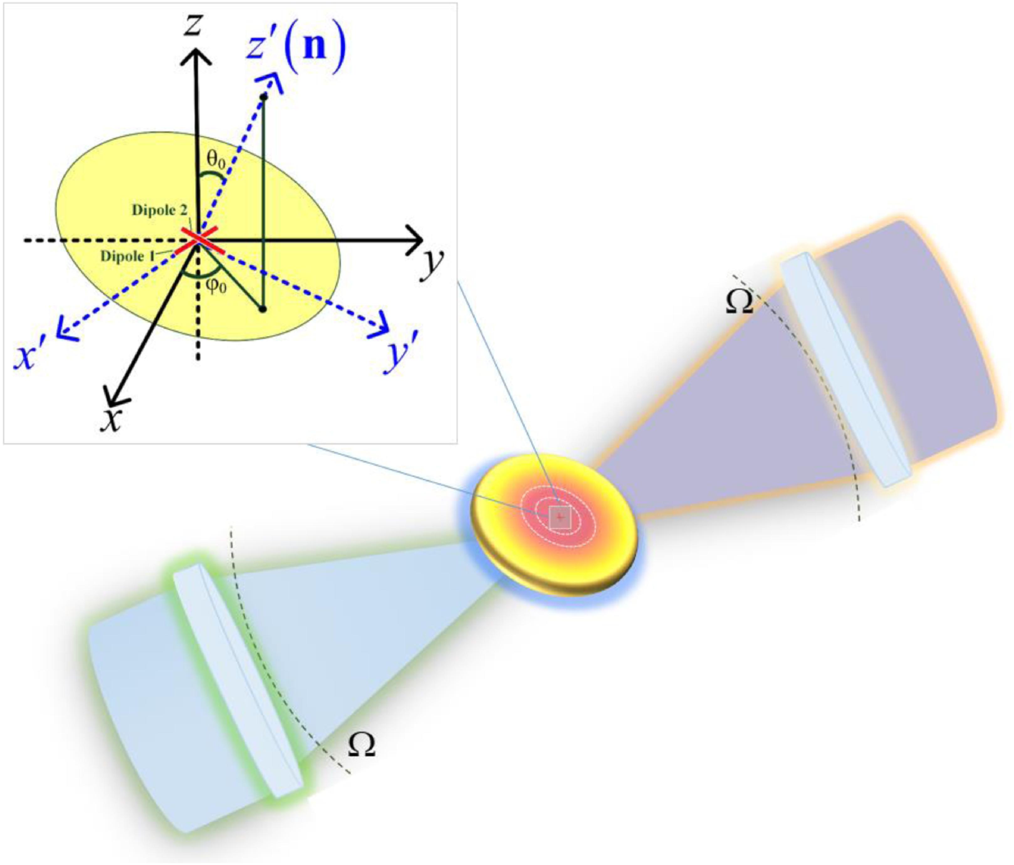
Fig. 1. Diagram of a 4 π -focusing system, with the inset illustrating the spatial rotation of an orthogonal dipole pair.

Fig. 2. Sub-diffraction-limited focal field with purely longitudinal SAM. (a) Intensity and polarization distribution of the required incident field. (b) Intensity and polarization distribution of the focus field in the three principal planes, and the opposite rotation directions of polarization are represented by white and black ellipses. (c) Line scanning of the focal field along the x , y , and z axes. (d)–(f) S x , S y , and S z distributions in the focal plane. (g)–(i) Directional angles of the SAM vectors in the focal plane.

Fig. 3. Sub-diffraction-limited focal field with prescribed SAM, exemplified by ( θ 0 , φ 0 ) = ( 30 ° , 120 ° ) . (a) Intensity and polarization distribution of the required incident field. (b) Intensity and polarization distribution of the focus fields in the three principal planes. (c) Line scanning of the focal field along the x , y , and z axes. (d)–(f) S x , S y , and S z distributions in the x − y plane. (g)–(i) Directional angles of the SAM vectors in the x − y plane.

Fig. 4. Arrangement of MCAODP.

Fig. 5. Néel-type SAM skyrmion (a)–(f) and bimeron (g)–(l) with negative polarity in the x − y plane. (a) and (g) are the intensity and polarization distribution of the required pupil field for the SAM skyrmion and bimeron, respectively. (b) and (h) are the intensity and polarization distribution of the SAM skyrmion and bimeron in the focal plane, respectively. (c) and (i) are the 3D distribution of SAM in the focal plane; the arrows indicate the orientation of the normalized SAM and color coded with its z component. (d)–(f) and (j)–(l) are the directional angles of their SAM vectors in the x − y plane.

Fig. 6. SAM skyrmions and bimerons in the y − z and x − z planes. (a) is a Bloch-type SAM skyrmion on the y − z plane with p = 1 , v = 1 . (b) is a Néel-type SAM skyrmion on the x − z plane with p = 1 , v = 1 . (c) and (d) are Néel-type SAM bimerons on the y − z and x − z planes with p = 1 , v = 1 , respectively.

Fig. 7. SAM skyrmions and bimerons in arbitrary prescribed planes. (a) is a Néel-type SAM skyrmion with p = − 1 , v = 1 , and ( θ 0 , φ 0 ) = ( 40 ° , 60 ° ) . (b) is a Néel-type SAM skyrmion with p = − 1 , v = 1 , and ( θ 0 , φ 0 ) = ( 45 ° , 45 ° ) . (c) is a Néel-type SAM bimeron with p = 1 , v = 1 , ( θ 0 , φ 0 ) = ( 50 ° , 60 ° ) , and ( θ b , φ b ) = ( 90 ° , 0 ° ) . (d) is a Bloch-type SAM bimeron with p = − 1 , v = 1 , ( θ 0 , φ 0 ) = ( 45 ° , 45 ° ) , and ( θ b , φ b ) = ( 90 ° , 90 ° ) .

Fig. 8. Sub-diffraction-limited focal field with x direction SAM. (a) Intensity and polarization distribution of the required incident field. (b) Intensity and polarization distribution of the focus field in the three principal planes. (c) Line scanning of the focal field along the x , y , and z axes. (d)–(f) S x , S y , and S z distributions in the y − z plane. (g)–(i) Directional angles of the SAM vectors in the y − z plane.

Fig. 9. Sub-diffraction-limited focal field with purely transverse SAM, exemplified by ( θ 0 , φ 0 ) = ( 90 ° , 45 ° ) . (a) Intensity and polarization distribution of the required incident field. (b) Intensity and polarization distribution of the focus field in the three principal planes. (c) Line scanning of the focal field along the x , y , and z axes. (d)–(f) S x , S y , and S z distributions in the x − y plane. (g)–(i) Directional angles of the SAM vectors in the x − y plane.

Fig. 10. Néel-type SAM skyrmion and bimeron with positive polarity in the x − y plane. (a) and (c)–(e) are the 3D distribution of the SAM vector and its directional angles in the focal plane for the SAM skyrmion, respectively. (b) and (f)–(h) are the 3D distribution of the SAM vector and its directional angles in the focal plane for the SAM bimeron, respectively.

Fig. 11. SAM anti-skyrmion and anti-bimeron with positive polarity in the x − y plane. (a) and (c) are the 3D distribution of the SAM vector in the focal plane for the two focused field topologies, and (b) and (d) are the 2D distribution of in-plane components.

Fig. 12. SAM bimeron with p = v = 1 , φ r = 0 ° , θ b = 90 ° , and varying φ b . (a)–(d) φ b is 45°, 90°, 135°, and 180°, respectively.

Fig. 13. Néel-type SAM bimeron with p = v = 1 , φ r = 0 ° , φ b = 45 ° , and varying θ b . (a)–(d) θ b is 45°, 70°, 110°, and 135°, respectively.

Fig. 14. SAM skyrmion and bimeron with p = − 1 , v = 1 , and varying vorticity φ r . (a)–(d) and (e)–(h) are the 3D distributions of the SAM and its in-plane component distribution. (a), (c) φ r = 45 ° ; (b), (d) φ r = 90 ° .

Set citation alerts for the article
Please enter your email address