
Jian Yan, Tianchi Song, Youduo Peng, Wei Zhou. Optical Accuracy Study of Pentagonal Tower Solar Heliostat Based on Support Bolt Jacking Molding[J]. Acta Optica Sinica, 2025, 45(6): 0608001
- Acta Optica Sinica
- Vol. 45, Issue 6, 0608001 (2025)
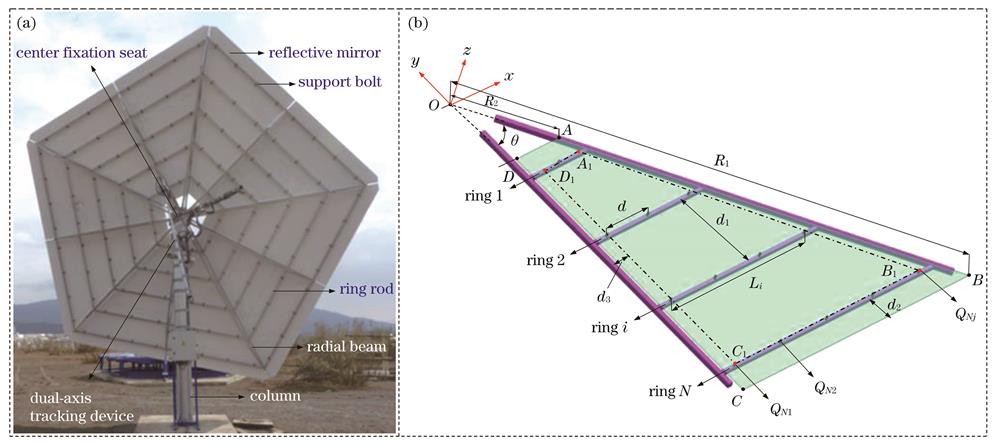
Fig. 1. Structure of pentagonal solar heliostat and its geometrical parameters. (a) Photograph of typical pentagonal heliostat;

Fig. 2. Schematic and optical information of a flat mirror shaped into a curved mirror by bolt jacking. (a)Forming schematic; (b) optical information on local triangular microelement surfaces
Fig. 3. Finite element model of reflective mirror jacking forming. (a) Geometric modeling of reflective mirror; (b) support bolt locations for single sub-mirror; (c) triangular mesh of single sub-mirror
Fig. 4. Variation of total slope error St and slope error component Sxwith element size for N=8 and d=1200 mm
Fig. 5. Mirror slope error distributions for different number of bolt ring rods N and desired spacing of bolts d. (a) Slope error component Sxdistribution for N=8 and d=1200 mm; (b) slope error component Sy distribution for N=8 and d=1200 mm; (c) slope error distribution for N=4 and d=400 mm; (d) slope error distribution for N=8 and d=400 mm; (e) slope error distribution for N=8 and d=1200 mm
Fig. 6. Variation of total slope error Stwith the number of bolt ring rods N and desired spacing of bolts d when the f= 250 m
Fig. 7. Variation of total slope error St with total number of support bolts
Fig. 8. Variations of total slope error St with target spherical focal length f. (a) Combination of d=800 mm and number of bolt ring rods N; (b) combination of N=5 and bolt spacing d
Fig. 9. Variations of total slope error St with area of reflective mirror at different target focal lengths f when d=400 mm. (a) f=50 m;
Fig. 10. Variations of total slope error St with gravity loads. (a) d=400 mm; (b) d=1200 mm
Fig. 11. Clouds of slope error distributions for different number of bolt ring rods N and desired spacing of bolts d at target focal lengths f =750 m under gravity loads along -z axis only. (a) N=4 and d=400mm; (b) N=6 and d=400 mm; (c) N=8 and d=400 mm; (d) N=4 and d=1200 mm; (e) N=6 and d=1200 mm; (f) N=8 and d=1200 mm
Fig. 12. Variations of total slope error St with uniform wind loads (including gravity loads). (a) Desired spacing of bolt d=400 mm;
Fig. 13. Clouds of slope error distributions for combined gravity loads and uniform wind loads along -z axis for target focal length f=750 m. (a) N=4 and d=400mm, wind loads 100 Pa; (b) N=6 and d=400 mm, wind loads 250 Pa; (c) N=4 and d=1200 mm, wind loads 100 Pa; (d) N=4 and d=1200 mm, wind loads 250 Pa; (e) N=6 and d=1200 mm, wind loads 250 Pa; (f) N=8 and d=1200 mm, wind loads 250 Pa
| |||||||||||||||||||||||||||
Table 1. Total number of mirror support bolts under combinations of different number of bolt ring rods and desired spacing of bolt


Set citation alerts for the article
Please enter your email address

© Copyright 2018-2021 | Chinese Laser Press. All Rights Reserved 沪ICP备15018463号-20