• Photonics Research
  • Vol. 13, Issue 4, 924 (2025)
Ziyao Zhang1, Minjia Chen1, Rui Ma1, Bohao Sun1..., Adrian Wonfor1, Richard Penty1 and Qixiang Cheng1,2,*|Show fewer author(s)
Author Affiliations
  • 1Department of Engineering, Centre for Photonic Systems, Electrical Engineering Division, University of Cambridge, Cambridge CB3 0FA, UK
  • 2GlitterinTech Limited, Xuzhou 221000, China
  • show less
    DOI: 10.1364/PRJ.543402 Cite this Article Set citation alerts
    Ziyao Zhang, Minjia Chen, Rui Ma, Bohao Sun, Adrian Wonfor, Richard Penty, Qixiang Cheng, "Dilated space-and-wavelength selective crosspoint optical switch," Photonics Res. 13, 924 (2025) Copy Citation Text show less
    Diagrams of the SWSS topologies. (a) Switch and selective SWSS featuring MRR-based wavelength selectors. (b) Dilated Banyan topology with MRRs assisted MZI as switching elements. (c) Traditional crossbar topology and (d) dilated crosspoint topology proposed in this work.
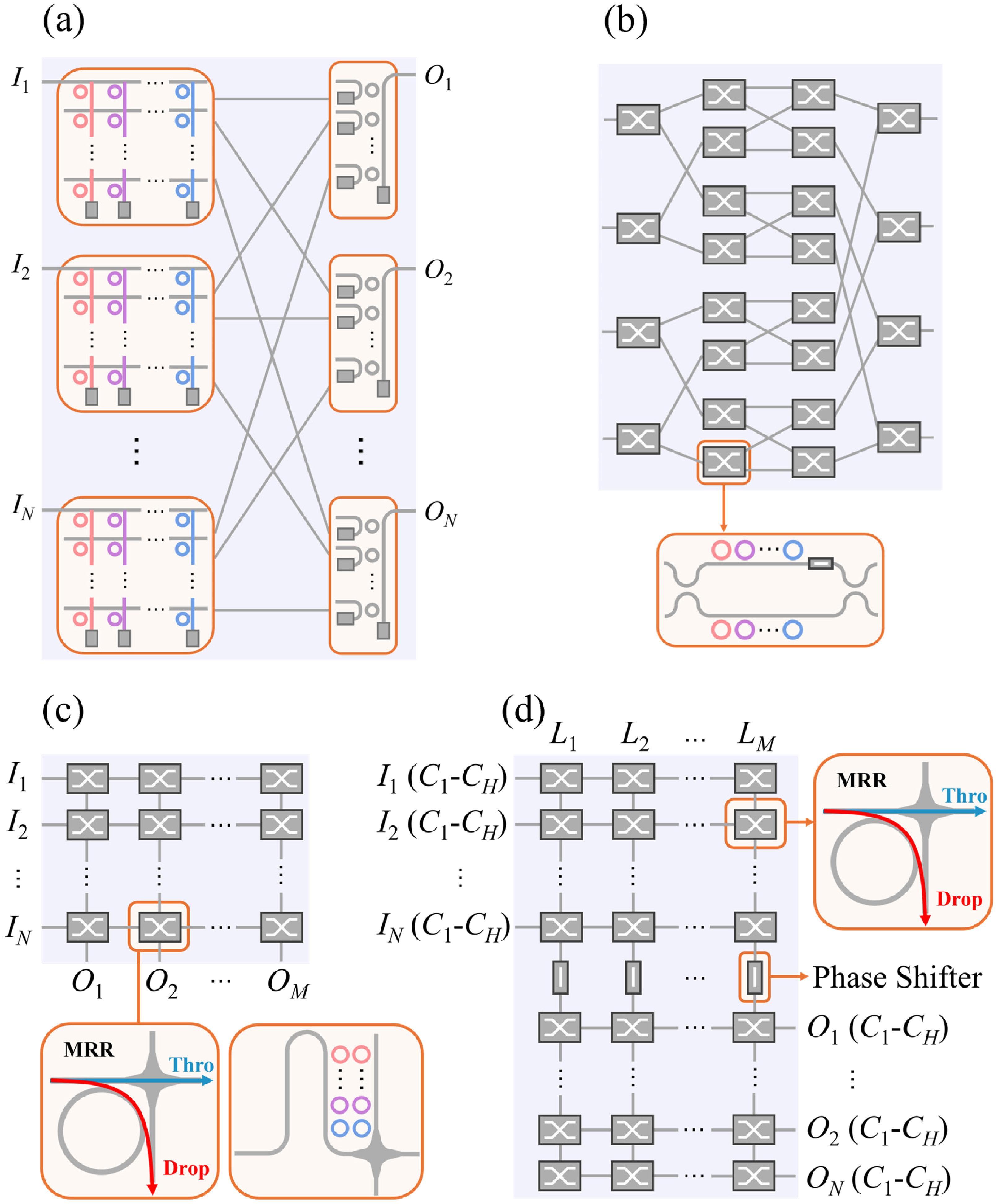
    Fig. 1. Diagrams of the SWSS topologies. (a) Switch and selective SWSS featuring MRR-based wavelength selectors. (b) Dilated Banyan topology with MRRs assisted MZI as switching elements. (c) Traditional crossbar topology and (d) dilated crosspoint topology proposed in this work.
    An example of crosstalk increased by interference.
    Fig. 2. An example of crosstalk increased by interference.
    Permutation number and effective switching states as functions of port number N. Different permutation numbers with different wavelength channels are compared. Se>PN−H indicates that the switch meets the wide-sense non-blocking condition.
    Fig. 3. Permutation number and effective switching states as functions of port number N. Different permutation numbers with different wavelength channels are compared. Se>PNH indicates that the switch meets the wide-sense non-blocking condition.
    Flow chart of the blocking status calculation process.
    Fig. 4. Flow chart of the blocking status calculation process.
    Switching element number as a function of the port number N among different reported SWSSs.
    Fig. 5. Switching element number as a function of the port number N among different reported SWSSs.
    Design space exploration of the MRR. (a) Contour of the 3 dB bandwidth versus MRR radius and κ2. (b) Contour of the attenuation at the resonance. (c) Contour of the drop port extinction ratio. (d) Overall design of the MRR. (e) Power coupling efficiency κ2 as a function of the MRR gap.
    Fig. 6. Design space exploration of the MRR. (a) Contour of the 3 dB bandwidth versus MRR radius and κ2. (b) Contour of the attenuation at the resonance. (c) Contour of the drop port extinction ratio. (d) Overall design of the MRR. (e) Power coupling efficiency κ2 as a function of the MRR gap.
    (a) Schematic of the 4×4×4λ dilated crossbar optical switch. (b) 3D model of the switching element. (c) Simulated transmission spectrum of the four wavelength channels. (d) An example showing signals in four wavelength channels are routed from I1 to O1,O2, O3, and O2, respectively. The second-order in-band crosstalk and the first-order out-band crosstalk in channel 1 are illustrated. (e) Diagram of the fully connected blocking SWSS operating under a fully loaded condition. (f) Diagram of the wide-sense non-blocking SWSS operating under a fully loaded condition.
    Fig. 7. (a) Schematic of the 4×4×4λ dilated crossbar optical switch. (b) 3D model of the switching element. (c) Simulated transmission spectrum of the four wavelength channels. (d) An example showing signals in four wavelength channels are routed from I1 to O1,O2, O3, and O2, respectively. The second-order in-band crosstalk and the first-order out-band crosstalk in channel 1 are illustrated. (e) Diagram of the fully connected blocking SWSS operating under a fully loaded condition. (f) Diagram of the wide-sense non-blocking SWSS operating under a fully loaded condition.
    (a) Microscope photograph of the dilated crossbar optical switch. (b) Photograph of the photonic chip with wire bonding and optical coupling with ultra-high-numerical-aperture (UHNA) fiber array.
    Fig. 8. (a) Microscope photograph of the dilated crossbar optical switch. (b) Photograph of the photonic chip with wire bonding and optical coupling with ultra-high-numerical-aperture (UHNA) fiber array.
    Diagram of the SWSS testing setup.
    Fig. 9. Diagram of the SWSS testing setup.
    Measured spectra of routing path from I4 to O1. (a) Spectrum when all paths are on-state. (b) Spectrum when wavelength channel 3 is at off-state with first-order crosstalk. (c) Spectrum when wavelength channel 3 is off-state with second-order crosstalk.
    Fig. 10. Measured spectra of routing path from I4 to O1. (a) Spectrum when all paths are on-state. (b) Spectrum when wavelength channel 3 is at off-state with first-order crosstalk. (c) Spectrum when wavelength channel 3 is off-state with second-order crosstalk.
    Measured optical power map of the optical switch for four wavelength channels.
    Fig. 11. Measured optical power map of the optical switch for four wavelength channels.
    The crosstalk ratios for all routing paths with leakage to all non-target output ports. The four wavelength channels are represented by distinct colors.
    Fig. 12. The crosstalk ratios for all routing paths with leakage to all non-target output ports. The four wavelength channels are represented by distinct colors.
    The superimposed spectrum of all routing permutations across four channels. Each sub-figure illustrates all 16 possible permutations within each wavelength channel.
    Fig. 13. The superimposed spectrum of all routing permutations across four channels. Each sub-figure illustrates all 16 possible permutations within each wavelength channel.
    Reconfiguration time of the SWSS.
    Fig. 14. Reconfiguration time of the SWSS.
    Diagrams of the switching states.
    Fig. 15. Diagrams of the switching states.
    NMaximum Number of Channels
    2, 13N1
    3, 4, 5, 7, 9, 11, 14, 15N2
    6, 8, 10N3
    12N4
    Table 1. Wide-Sense Non-blocking Condition for Dilated Crosspoint Topology with Different Port Numbers
    ReferenceTopologyElements NumberGlobal Switching StatesOrder of CrosstalkNumber of Stages
    [21] (NB)Dilated Banyan, B&S(4N24N)·H, 2HN2+2log2N(N!)HSecond2log2N, 2log2N+1
    [19] (NB)S&S(H+1)N2+N2(N!)HSecond3N1
    [26] (NB)PILOSSH·(N2+2N)(N!)HFirstN2
    [20,27] (NB)CrossbarHN2(N!)HFirst2N1
    [26] (FCB)PILOSSH·(N2/4+N)((N/2)!)HFirst2N2
    This work (NB)Dilated crosspoint2MNLook-up tableSecond4N2
    This work (FCB)Dilated crosspoint2HNLook-up tableSecond4N2
    Table 2. Figures of Merit for Various Reported SWSS Topologiesa
    ReferenceScaleNumber of ElementsPlatformOn-Chip LossWorst Crosstalk
    [11]4×4×1λ32Si/SiN1.8–20.4 dB−50 dB
    [14]1×4×4λ16SOI<1 dB−20 dB
    [18]8×8×8λ128 SOA gates + 8 AWGsInGaAsP/InP7.6–14.7 dBPenalty: 3.3 dB
    [20]8×4×2λ64SOI6–14 dB−20/−32 dB
    [33]2×2×2λ4SOIAvg. 5.1 dB−21 dB
    This work4×4×4λ32SOI2.3–8.6 dB−35.3 dB
    Table 3. Performance Comparison with Other Reported Integrated Switches
    Ziyao Zhang, Minjia Chen, Rui Ma, Bohao Sun, Adrian Wonfor, Richard Penty, Qixiang Cheng, "Dilated space-and-wavelength selective crosspoint optical switch," Photonics Res. 13, 924 (2025)
    Download Citation