• Opto-Electronic Advances
  • Vol. 6, Issue 11, 230018 (2023)
Hengtian Zhu1,†, Junxian Luo2,†, Qing Dai3,†, Shugeng Zhu1..., Huan Yang1, Kanghu Zhou1, Liuwei Zhan1, Biao Xu3, Ye Chen1, Yanqing Lu1 and Fei Xu1,*|Show fewer author(s)
Author Affiliations
  • 1College of Engineering and Applied Sciences and Collaborative Innovation Center of Advanced Microstructures, Nanjing University, Nanjing 210023, China
  • 2School of Physics, Nanjing University, Nanjing 210023, China
  • 3Department of Cardiology, Affiliated Drum Tower Hospital, Medical School of Nanjing University, Nanjing 210008, China
  • show less
    DOI: 10.29026/oea.2023.230018 Cite this Article
    Hengtian Zhu, Junxian Luo, Qing Dai, Shugeng Zhu, Huan Yang, Kanghu Zhou, Liuwei Zhan, Biao Xu, Ye Chen, Yanqing Lu, Fei Xu. Spatiotemporal hemodynamic monitoring via configurable skin-like microfiber Bragg grating group[J]. Opto-Electronic Advances, 2023, 6(11): 230018 Copy Citation Text show less
    Skin-like microfiber Bragg grating (μFBG) patch. (a) Schematic illustration of the soft μFBG patch. The optical microfiber contains a femtosecond laser-inscribed FBG embedded in a thin PDMS patch and is connected end-to-end with two commercial single-mode optical fibers (SMFs) for light propagation. (b) Optical micrograph of the soft μFBG patch. The FBG is inscribed in the axis of the microfiber. (c) SEM of the microfiber, which has a diameter of 12 μm. (d) Image of the soft μFBG patch draped on a life-sized, transparent mannequin hand conformally. (e) Image of three soft μFBG patches connected in series to illustrate the multichannel sensing capabilities. (f) Reflective optical spectrum of the three soft μFBG patches. The μFBG patches are capable of detecting strain separately without interference due to the different working wavelengths. (g–i) Images of the soft μFBG patch under modes of bending, twisting, and waving, demonstrating the mechanical compliance and robustness of the device.
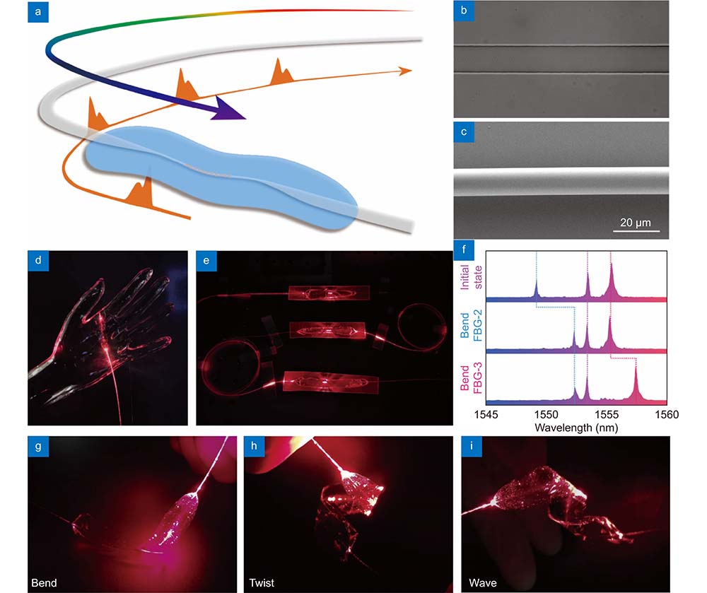
    Fig. 1. Skin-like microfiber Bragg grating (μFBG) patch. (a) Schematic illustration of the soft μFBG patch. The optical microfiber contains a femtosecond laser-inscribed FBG embedded in a thin PDMS patch and is connected end-to-end with two commercial single-mode optical fibers (SMFs) for light propagation. (b) Optical micrograph of the soft μFBG patch. The FBG is inscribed in the axis of the microfiber. (c) SEM of the microfiber, which has a diameter of 12 μm. (d) Image of the soft μFBG patch draped on a life-sized, transparent mannequin hand conformally. (e) Image of three soft μFBG patches connected in series to illustrate the multichannel sensing capabilities. (f) Reflective optical spectrum of the three soft μFBG patches. The μFBG patches are capable of detecting strain separately without interference due to the different working wavelengths. (gi) Images of the soft μFBG patch under modes of bending, twisting, and waving, demonstrating the mechanical compliance and robustness of the device.
    Stress and vibration characterization of skin-like μFBG patch. (a) Reflective optical spectra of the soft μFBG patch under different stresses. (b) Stress response of the soft μFBG patch. (Inset: stress response of the commercial FBG with a diameter of 80 μm and 125 μm separately for comparison.) (c) Details of the stress response of the soft μFBG patch when detecting small stresses. The red region indicates the stress range of the life pulse. (d) Stress response of the soft μFBG patch when stress increases and decreases to illustrate the hysteresis property. (e) Dynamic stress response of the soft μFBG patch compared with a commercial force meter. (f) Sensitivity of the soft μFBG patch, which is enhanced by two orders of magnitude compared with commercial FBGs with diameters of 80 μm and 125 μm. (g–i) Vibration characterization of the soft μFBG patch under frequencies of 1 Hz, 2 Hz, and 5 Hz. (j) 10000-circle repetition tests of the soft μFBG patch to illustrate great repeatability.
    Fig. 2. Stress and vibration characterization of skin-like μFBG patch. (a) Reflective optical spectra of the soft μFBG patch under different stresses. (b) Stress response of the soft μFBG patch. (Inset: stress response of the commercial FBG with a diameter of 80 μm and 125 μm separately for comparison.) (c) Details of the stress response of the soft μFBG patch when detecting small stresses. The red region indicates the stress range of the life pulse. (d) Stress response of the soft μFBG patch when stress increases and decreases to illustrate the hysteresis property. (e) Dynamic stress response of the soft μFBG patch compared with a commercial force meter. (f) Sensitivity of the soft μFBG patch, which is enhanced by two orders of magnitude compared with commercial FBGs with diameters of 80 μm and 125 μm. (gi) Vibration characterization of the soft μFBG patch under frequencies of 1 Hz, 2 Hz, and 5 Hz. (j) 10000-circle repetition tests of the soft μFBG patch to illustrate great repeatability.
    Ballistocardiogram (BCG) signal and pulse wave detection using a μFBG patch. (a) Schematic diagram of BCG signal detection. A soft μFBG patch is attached to the chest skin at the tricuspid site. (b) BCG signal detected by the soft μFBG patch, and the triangle marks indicate the cardiac cycle. (c) Details of the BCG signal. The purple region indicates the systole of the rhythm of the heart, which can be identified according to the characteristic I wave and K wave. (d) Frequency spectrum of the BCG signal. (e) Schematic diagram of pulse wave detection. A soft μFBG patch is attached to the skin at the sites of the superficial arteries. (f) Pulse wave detected by the soft μFBG patch, and the triangle marks indicate the cardiac cycle. (g) Details of the pulse wave. The purple region indicates the systole of the rhythm of the heart, which can be identified according to the characteristic B wave and E wave. (h) Frequency spectrum of pulse wave.
    Fig. 3. Ballistocardiogram (BCG) signal and pulse wave detection using a μFBG patch. (a) Schematic diagram of BCG signal detection. A soft μFBG patch is attached to the chest skin at the tricuspid site. (b) BCG signal detected by the soft μFBG patch, and the triangle marks indicate the cardiac cycle. (c) Details of the BCG signal. The purple region indicates the systole of the rhythm of the heart, which can be identified according to the characteristic I wave and K wave. (d) Frequency spectrum of the BCG signal. (e) Schematic diagram of pulse wave detection. A soft μFBG patch is attached to the skin at the sites of the superficial arteries. (f) Pulse wave detected by the soft μFBG patch, and the triangle marks indicate the cardiac cycle. (g) Details of the pulse wave. The purple region indicates the systole of the rhythm of the heart, which can be identified according to the characteristic B wave and E wave. (h) Frequency spectrum of pulse wave.
    Systemic pulse transmit time (PTT) calculation using the soft μFBG group. (a) Schematic diagram of the measurement positions for the three cases. Systemic PTTs are calculated via the cooperative analysis of BCG signals and pulse waves at the three different superficial artery sites. (b, c) Case 1: simultaneous measurement of BCG and pulse wave at the carotid artery (CA). (d, e) Case 2: simultaneous measurement of BCG and pulse wave at the radial artery (RA). (f, g) Case 3: simultaneous measurement of BCG and pulse wave at the pedal artery (PA). The graphs (c, e, g) show the details of the BCG signal and pulse wave within one cardiac cycle. The PTTs of the three cases, indicated by the purple region, are identified by the I wave of the BCG and the B wave of the pulse wave. (h) Comparison of the average PTT results of the three cases to illustrate the systemic hemodynamic evaluation ability of the soft μFBG group.
    Fig. 4. Systemic pulse transmit time (PTT) calculation using the soft μFBG group. (a) Schematic diagram of the measurement positions for the three cases. Systemic PTTs are calculated via the cooperative analysis of BCG signals and pulse waves at the three different superficial artery sites. (b, c) Case 1: simultaneous measurement of BCG and pulse wave at the carotid artery (CA). (d, e) Case 2: simultaneous measurement of BCG and pulse wave at the radial artery (RA). (f, g) Case 3: simultaneous measurement of BCG and pulse wave at the pedal artery (PA). The graphs (c, e, g) show the details of the BCG signal and pulse wave within one cardiac cycle. The PTTs of the three cases, indicated by the purple region, are identified by the I wave of the BCG and the B wave of the pulse wave. (h) Comparison of the average PTT results of the three cases to illustrate the systemic hemodynamic evaluation ability of the soft μFBG group.
    Hemodynamic monitoring during exercise using soft μFBG group. (a) Representative BCG signal (blue), pulse wave at the PA site (red), and respiration signal (yellow) monitored simultaneously. (b, c) Details of the synchronized BCG signal and pulse wave during the normal state and exercise state, respectively. PTT is indicated by the dashed lines. (d) Comparison of heart rate (HR) calculated from the vital signal acquired by the μFBG group (blue) and a commercial sphygmomanometer (red). (e) Comparison of PTT (blue), which is calculated from the BCG signal and pulse wave acquired by the μFBG group, and the systolic and diastolic blood pressure (SBP and DBP) acquired from a commercial sphygmomanometer. The exercise periods are indicated by the purple region.
    Fig. 5. Hemodynamic monitoring during exercise using soft μFBG group. (a) Representative BCG signal (blue), pulse wave at the PA site (red), and respiration signal (yellow) monitored simultaneously. (b, c) Details of the synchronized BCG signal and pulse wave during the normal state and exercise state, respectively. PTT is indicated by the dashed lines. (d) Comparison of heart rate (HR) calculated from the vital signal acquired by the μFBG group (blue) and a commercial sphygmomanometer (red). (e) Comparison of PTT (blue), which is calculated from the BCG signal and pulse wave acquired by the μFBG group, and the systolic and diastolic blood pressure (SBP and DBP) acquired from a commercial sphygmomanometer. The exercise periods are indicated by the purple region.
    Peripheral resistance monitoring using soft μFBG group. (a) Schematic diagram of peripheral resistance monitoring. An inflatable cuff is used to impose the external pressure on the artery. The BCG signal and pulse wave at the RA site are continuously detected to calculate the PTT. (b) BCG signal (blue) and pulse wave (yellow) detected simultaneously by μFBG group. (c) PTT of every cardiac cycle (green dot) calculated from the vital signal. The trend of PTT indicated by the red line is calculated by moving averaging. The compression periods are indicated by the green region.
    Fig. 6. Peripheral resistance monitoring using soft μFBG group. (a) Schematic diagram of peripheral resistance monitoring. An inflatable cuff is used to impose the external pressure on the artery. The BCG signal and pulse wave at the RA site are continuously detected to calculate the PTT. (b) BCG signal (blue) and pulse wave (yellow) detected simultaneously by μFBG group. (c) PTT of every cardiac cycle (green dot) calculated from the vital signal. The trend of PTT indicated by the red line is calculated by moving averaging. The compression periods are indicated by the green region.
    Hengtian Zhu, Junxian Luo, Qing Dai, Shugeng Zhu, Huan Yang, Kanghu Zhou, Liuwei Zhan, Biao Xu, Ye Chen, Yanqing Lu, Fei Xu. Spatiotemporal hemodynamic monitoring via configurable skin-like microfiber Bragg grating group[J]. Opto-Electronic Advances, 2023, 6(11): 230018
    Download Citation