 AI Video Guide
  AI Picture Guide
 AI One Sentence

Min TAN, Xiaowu CHEN, Jinshan YANG, Xiangyu ZHANG, Yanmei KAN, Haijun ZHOU, Yudong XUE, Shaoming DONG. Microstructure and Oxidation Behavior of ZrB2-SiC Ceramics Fabricated by Tape Casting and Reactive Melt Infiltration [J]. Journal of Inorganic Materials, 2024, 39(8): 955
- Journal of Inorganic Materials
- Vol. 39, Issue 8, 955 (2024)
Note: This section is automatically generated by AI . The website and platform operators shall not be liable for any commercial or legal consequences arising from your use of AI generated content on this website. Please be aware of this.
Abstract
In recent years, hypersonic vehicles have become a key area of development in the aerospace sector of many countries due to the rapid advancement of aerospace technology and the urgent need to integrate air and space[1⇓-3]. Certain vehicle segments, such as wing leading edges and nose cones, rub heavily against the atmosphere during long hypersonic cruises, trans-atmospheric flights, and atmospheric re-entries, generating extremely high temperatures[3⇓-5]. Therefore, thermal protection materials for hypersonic vehicles must be physiochemically stable under high temperatures and oxidizing conditions for extended periods of time[6⇓-8].
Current high-temperature structural materials comprise refractory metals, Cf/C composites, Cf/SiC composites, and ultra-high temperature ceramics[9]. Refractory metals such as tungsten (W) and rhenium (Re) were the first high-temperature resistant materials which had been studied and applied, but these materials have poor oxidation resistance and low specific strength and specific modulus[10]. In inert atmosphere, Cf/C composites can withstand temperatures above 3000 ℃. However, they are difficult to be used in oxidizing conditions above 500 ℃ due to their poor oxidation resistance[3,11-12]. In comparison to Cf/C composite materials, Cf/SiC composite materials have a significantly improved resistance to oxidation. However, they are also prone to rapid oxidation at temperatures above 1600 ℃[13]. Ultra-high temperature ceramics (UHTCs) are a class of materials with melting points above 3000 ℃, mainly composed of transition metal carbides and borides (ZrC, ZrB2, HfC, HfB2, etc). The characteristics of high strength, high hardness and high melting points, making them ideal for use in extreme aerospace environments[2,4,14].
ZrB2 is considered to be a promising structural material for long-term use in extreme thermal environments due to its low theoretical density (6.09 g∙cm-3) and high thermal conductivity (65-135 W∙m-1∙K-1) among ultra- high temperature ceramics[15⇓⇓-18]. ZrB2-SiC ceramics, which are produced by the introduction of SiC into ZrB2 ceramics, have excellent oxidation resistance at temperatures below 1500 ℃[19-20]. Due to their strong covalent bonding and low self-diffusion coefficient, ZrB2- based ceramics require high-temperature and high-pressure sintering to form dense stacks[21⇓-23]. Zhao et al.[24] sintered ZrB2-20%(in vol)SiC by spark plasma sintering (SPS) at 1400, 1600 and 1800 ℃ to produce ceramics with different porosities, and these ceramics were tested for high temperature oxidation. The ceramics sintered at 1800 ℃ exhibited the best oxidation resistance, with the smallest change in the thickness of the ZrO2-SiO2 oxide layer. To lower the sintering temperature of ZrB2 ceramics, Silvestroni et al.[25] utilized ZrSi2, MoSi2, TaSi2, and WSi2 as sintering aids, to obtain four kinds of ZrB2 ceramics by hot press sintering respectively. The impact of these four sintering aids on the oxidation resistance of ZrB2 ceramics was then investigated, and the results showed that MoSi2 could significantly improve the oxidation resistance of ZrB2 ceramics. The reason is that Mo increases the viscosity of glassy SiO2, which leads to the inhibition of columnar ZrO2 formation. Reactive melt infiltration can densify ceramics at lower temperatures compared to sintering aids, and without the need for pressure. D'amico et al.[26] produced ZrB2-SiC ceramics by reactive melt infiltration of Si at 1500 ℃ under vacuum and studied the oxidation resistance of the ceramics oxidized at 1500 ℃ for 48 h. The results showed that the oxidation rate of ZrB2-SiC ceramics prepared by reactive melt infiltration was slower than that of ceramics prepared by other methods. Compared with the conventional preparation method, it is easier to obtain ultra-high temperature ceramics with fine particle size and homogeneous composition by reactive preparation. Lee et al.[27] used ZrSi2-B4C-C as a sintering aid to prepare ZrB2-SiC ceramics through reactive spark plasma sintering (R-SPS) at 1450 ℃. The sizes of ZrB2 and SiC grains ranged from 80 to 350 nm with a uniform distribution of phases, due to the molecular homogeneity of ZrSi2 and the homogeneous mixing of raw material powders. However, the impact of phase dimensions on oxidation resistance in multiphase UHTCs is unclear. Therefore, further studies are necessary to investigate the differences in oxidation behaviors of ceramics with smaller grain sizes prepared by the reaction compared to ceramics prepared directly using powders of UHTCs.
In this work, ZrB2-SiC ceramics were produced by tape casting combined with reactive melt infiltration. The formation of ZrB2 and SiC phases involves the reaction between ZrSi2, B4C, and C, as shown in the following formula:
Then, the ZrB2-SiC ceramics were further densified by reactive melt infiltration of Si. Meanwhile, as a control group, ZrB2-SiC ceramics were prepared using ZrB2 and SiC powders as raw materials by the same process as described above. The microscopic morphology and compositional distribution of the ceramics were firstly analyzed. Subsequently, the oxidation behavior of the ceramics was revealed by analyzing the evolution of the phase composition and microstructure during oxidation in air at 1600 ℃. The differences between oxidation behaviors of the two ceramics were also discussed.
1 Experimental
1.1 Materials and ceramics preparation
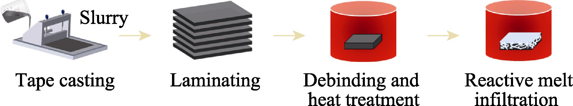
ZrB2-SiC ceramics were produced by combining tape casting with reactive melt infiltration of Si, as schematically shown in Fig. 1.
![]()
Figure 1.Flow chart for the processing of ceramics
ZrSi2 (99.5%, <1 µm, Forsman, Beijing), B4C (99.9%, 2-4 µm, Aladdin, Shanghai), carbon black (99.5%, 30 nm, Aladdin, Shanghai), ZrB2 (99.5%, <1 µm, Shuitian, Shanghai) and SiC (99%, 0.5-0.7 µm, Aladdin, Shanghai) were used as raw materials. The first step was to prepare slurry, i.e. ZrSi2, B4C and carbon black powders were added into a polyethylene jar at molar ratio of 2 : 1 : 3 (shown in Table 1), using ethanol, phenolic resin and polyvinyl butyral (PVB) as a solvent, binder, and pore-making agent, respectively. The mixture was ball milled for 12 h. The slurry was degassed under vacuum after ball milling. Subsequently, it was used for tape casting with the blade height set at 300 µm and the casting rate set at 100 mm/min. After tape casting, the film was air-dried at room temperature for 12 h. The dried film was cut into 60 mm × 60 mm sheets and then the sheets were laminated into a block about 4 mm thick. The block was heated to 700 ℃ and held for 1 h in flowing argon atmosphere for debinding, and then heated to 1500 ℃ and held for 1 h to produce ZrB2 and SiC in the porous preforms via reaction formula (1). Finally, the porous preforms were held in vacuum at 1500 ℃ for 30 min for reaction melt infiltration, and the ceramics (referred to as ZBC ceramics) were prepared by the reaction of molten Si with pyrolysis carbon (from phenolic resin) to produce SiC. In this experiment, ceramics (referred to as ZS ceramics) were prepared using ZrB2 and SiC powders at a molar ratio of 1 : 2 as raw materials, following the above steps.
| ZBC | ZS | ||||
|---|---|---|---|---|---|
| Raw materials | ZrSi2 | B4C | C | ZrB2 | SiC |
| Molar ratio | 2 | 1 | 3 | 1 | 2 |
Table 1.
Raw materials and their molar ratios for ceramics preparation
1.2 Cyclic oxidation tests
The prepared ceramics were cut into samples with dimensions of 5 mm×5 mm×3 mm and then placed into a muffle furnace for high temperature oxidation. The temperature was increased to 1600 ℃ at rate of 5 ℃/min and held for 2 h. After natural cooling, the samples were removed and weighed. After recording the mass of each sample, the samples were returned to the muffle furnace and the above steps were repeated, and the oxidation cycle was repeated 5 times for total of 10 h. The mass change per unit surface area (ΔW) was calculated by the following formula:
1.3 Characterization
The weight of the samples before and after the oxidation tests was recorded using analytical balance with accuracy of 0.01 mg. The average of 5 or more samples was calculated at each time. Phase compositions of the samples were characterized by X-ray diffraction (XRD, Ultima, IV, Rigaku Corporation, Kyoto, Japan, and D8 DISCOVER, Bruck, Germany) using Cu Kα radiation. The surface and cross-section microstructures of the samples were characterized by field emission scanning electron microscope (SEM, Magellan 400, FEI, USA), and the chemical compositions of the samples were characterized by equipped X-ray energy spectrometer (EDS, PN-5502, INCA ENGERY, UK). Some of the samples need to be metallurgically polished before characterization.
2 Results and analysis
2.1 Microstructure of ceramics
Fig. 2(a, b) show the XRD patterns and cross- sectional morphology of ZBC porous preforms after heat-treatment. As shown in Fig. 2(a), heat treatment of ZBC porous preforms can produce ZrB2 and SiC. Fig. 2(b) shows that, besides ZrB2 and SiC, the porous preforms contain pyrolysis carbon derived from phenolic resin, and these pyrolysis carbon would be used as carbon source to react with Si to form SiC in the reaction melt infiltration process. Fig. 2(c) displays the XRD patterns of two ceramics ZBC and ZS. Both ceramics possess the same phases: ZrB2, SiC and Si. Compared to Fig. 2(a), there is a significant increase in the intensity of the SiC peaks after reaction melt infiltration. This suggests that Si react with carbon to form SiC in the porous preforms during the reaction melt infiltration process. XRD patterns show Si peaks due to the presence of Si residue left by the reactive melt infiltration process.
![]()
Figure 2.Microstructure and morphology of ZBC samples(a) XRD patterns of ZBC porous preforms before and after heat treatment; (b) Cross-sectional morphology of ZBC porous preforms after heat treatment; (c) XRD patterns of ceramics after reactive melt infiltration
Fig. 3 displays the surface and cross-sectional morphologies of the ZBC ceramics. Fig. 3(a-c) demonstrate that the surfaces of the ceramics have uniform compositional distribution and dense structure. Fig. 3(d-f) show that the cross-sections of the ceramics are still dense with no apparent delamination, indicating that the interlayer bonding of the ceramics is tight. Fig. 4 displays the surface and cross-sectional SEM morphologies of the ZS ceramics. It is seen that the morphology of ZS ceramics is similar to that of ZBC ceramics. But the particle size of ZrB2 in ZS ceramics is larger than that in ZBC ceramics, indicating that the ZrB2 produced through the reaction has a smaller particle size. Additionally, both Fig. 3 and Fig. 4 indicate that the ceramics mainly contain three phases. According to the EDS results, it can be inferred that the bright white region, gray region and black region are ZrB2 (Spot 1, Spot 4), Si (Spot 2, Spot 5),SiC (Spot 3, Spot 6), respectively. This is consistent with the XRD patterns in Fig. 2(c).
![]()
Figure 3.Morphologies and corresponding EDS analyses of ZBC ceramics(a-c) Surface; (d-f) Cross section
![]()
Figure 4.Morphologies and corresponding EDS analyses of ZS ceramics(a-c) Surface; (d-f) Cross section
2.2 Cyclic oxidation behavior of ceramics
Fig. 5 displays the XRD patterns of the ceramics after oxidation at 1600 ℃ in the air. Fig. 5 shows the intensity of the ZrSiO4 peaks in ZS ceramics is more pronounced compared to ZBC ceramics. According to the binary phase diagram in Fig. 6[28], ZrSiO4 is formed by the reaction of ZrO2 with SiO2. The oxidation process involves the following reactions:
![]()
Figure 5.XRD patterns of ceramics oxidized at 1600 ℃ in the air for different periods(a) ZBC; (b) ZS
![]()
Figure 6.ZrO2-SiO2 binary phase diagram[
Fig. 7 shows the surface morphology of ZBC ceramics after oxidation at 1600 ℃ in the air. Fig. 7(a-c) displays the surface morphologies of the ZBC ceramics after oxidation for 2 h. The surface of ZBC ceramics after oxidation displays three distinct zones: oxidation zone, transition zone, and slightly oxidized zone. According to EDS results, it can be inferred that the oxidation zone contains a significant quantity of ZrSiO4 (Spot 1, Spot 5, and Spot 9). The transition zone contains precrystallization products with a dendritic structure. As revealed by EDS analysis, this structure is formed by the combination of ZrO2 and SiO2 at molar ratio less than 1 : 1 (Spot 6). The slightly oxidized zone is uniform with no cracks, and the EDS results indicate that this phase is SiO2 with traces of ZrO2 solidly dissolved (Spot 3). Fig. 7(d-f) displays the surface morphologies of the ZBC ceramics after oxidation for 6 h, which is similar to the morphology after oxidation for 2 h. The difference lies in the fact that the slightly oxidized zone is no longer homogeneous with a few cracks. With the oxidation time increasing to 10 h, the morphology of the slightly oxidized zone is gradually approaching the transition zone, and many cracks appear (Fig. 7(g-i)).
![]()
Figure 7.Surface morphologies of ZBC ceramics oxidized at 1600 ℃ for different periods(a-c) 2 h; (d-f) 6 h; (g-i) 10 h
Based on the surface morphology evolution of the ZBC ceramics after oxidation for different time, it can be inferred that the ZBC ceramics undergo three stages during the oxidation process. During the first stage, SiC, Si, and ZrB2 undergo oxidation to form SiO2 and ZrO2. As shown in Fig. 3, ZrB2 particles are uniformly distribute between SiC and Si, resulting in a diffuse distribution of ZrO2 between SiO2. This leads to the formation of a SiO2-ZrO2 glassy oxide layer. During cooling, the edge region undergoes more severe oxidation, leading to a higher ZrO2 content precipitating out of SiO2. SiO2 loses ZrO2 and begins to crystallize, and forms a eutectic with ZrO2, leading to the formation of ZrSiO4. This leads to cracking in the edge region due to the mismatch of the coefficients of thermal expansion. In the central region, SiO2 remains in glassy state due to the high viscosity of the SiO2-ZrO2 oxide layer. During the second stage, as the number of cyclic oxidations increases, a small amount of ZrO2 in the central region of the oxide layer migrates and enriches during the cooling process, eventually precipitating crystals in the region of higher concentration. At the same time, the loss of ZrO2 causes crystallization of SiO2. During the third stage, the number of cyclic oxidations continues to increase, causing a significant migration of ZrO2 during the cooling process. Simultaneously, a considerable amount of SiO2 begins to crystallize and forms a eutectic with ZrO2, leading to the formation of ZrSiO4, and ultimately resulting in cracks in the center region of the oxide layer.
Fig. 8 shows the surface morphology of ZS ceramics after oxidation at 1600 ℃ in the air. It indicates that the oxidation surface of ZS ceramics differs from that of ZBC ceramics. The surface of ZS ceramics exhibits numerous ZrSiO4 particles. As the oxidation time increasing, cracks in the surface of ZS ceramics gradually widen and bubbles appear. Based on the results presented in Fig. 4, it is evident that the ZrB2 particle size in ZS ceramics is large. As a result, the diffusion of ZrO2 generated after oxidation in SiO2 is difficult. Consequently, a high viscosity SiO2-ZrO2 glassy oxide layer is not formed, leading to a significant amount of SiO2 crystallization during the cooling stage. Ultimately, it forms a eutectic mixture with ZrO2, resulting in the creation of ZrSiO4. This result is also consistent with the XRD pattern of Fig. 5(b).
![]()
Figure 8.Surface morphologies of ZS ceramics oxidized at 1600 ℃ for different periods(a-c) 2 h; (d-f) 6 h; (g-i) 10 h
Fig. 9 shows the cross-sectional morphologies of ZBC and ZS ceramics oxidized in the air at 1600 ℃. With the duration of oxidation, all ceramics show an increase of thickness of the oxide layer on the surface. Moreover, the thickening of the oxide layer oxidized from 2 h to 6 h is larger than that oxidized from 6 h to 10 h. After oxidation for 10 h, the oxide layer of the edge zone in ZBC ceramics (Fig. 9(c)) mainly contains three phases. Based on the EDS results, it can be inferred that the bright white region, gray region and black region are ZrSiO4 (Spot 1), 9SiO2-ZrO2 (Spot 2) and SiO2 (Spot 3), respectively. The cross-sectional morphology of this zone corresponds to the oxidation and transition zone on the surface of ZBC ceramics in Fig. 7 due to the presence of obvious cracks in the oxide layer. Fig. 9(d-f) display the cross-sectional morphologies of the central zone of ZBC ceramics. The thickness of the oxide layer in the central zone is slightly thinner than that of the edge zone. After oxidation for 2 and 6 h, the oxide layer in the central zone still maintains dense and homogeneous morphology. After oxidation for 10 h, the oxide layer begins to crystallize and a minor number of cracks appears. Therefore, the cross-sectional morphology of this zone corresponds to the slightly oxidized zone on the surface of ZBC ceramics in Fig. 7. Fig. 9(g-i) show the cross-sectional morphologies of ZS ceramics. Thickness of the oxide layer of ZS ceramics is greater than that of ZBC ceramics. According to the EDS results, the oxide layer mainly contains four phases: ZrO2 (Spot 4), ZrSiO4 (Spot 5), 10SiO2-ZrO2 (Spot 6), and SiO2 (Spot 7) correspond to bright white region, white region, gray region, and black region, respectively. After oxidation for 2 h, SiO2 crystallizes in the oxide layer and a limited number of cracks appears. As oxidation time increasing, the thickness of the oxide layer also increases, and the cracks gradually expand. The cross-sectional SEM morphology of ZS ceramics is consistent with the results shown in Fig. 8.
![]()
Figure 9.Cross-sectional SEM morphologies of ceramics oxidized at 1600 ℃ for different periods(a, d, g) 2 h; (b, e, h) 6 h; (c, f, i) 10 h
The oxidation resistance can be evaluated quantitatively by analyzing the thickness of the oxide layer and the mass change during the oxidation process. Fig. 10 displays the thickness change of the oxide layer during the oxidation of ZBC and ZS ceramics. The thickness of the oxide layer increases rapidly in the first 6 h oxidation and then increases slowly in the following 4 h oxidation, exhibiting good oxidation resistance of the oxide layers of both ceramics. Furthermore, the thickness of the oxide layer of ZBC ceramics is thinner than that of ZS ceramics, which indicates that the former shows better oxidation resistance than the latter.
![]()
Figure 10.Thickness of the oxide layer of ceramics oxidized at 1600 ℃ for different periods
The mass change curves of two ceramics ZBC and ZS during the oxidation process are shown in Fig. 11. It shows that both ceramics gain weight more quickly in the first 6 h oxidation and slowly in the last 4 h oxidation. Additionally, the weight gain of ZS ceramics is higher than that of ZBC ceramics, which is consistent with the thickness variation of the oxide layer in Fig. 10. The experimental results indicate that the oxidation resistance of ZBC ceramics at 1600 ℃ is better than that of ZS ceramics. It can be concluded that the reaction of ZrSi2,B4C, and C results in the preparation of ZrB2-SiC ceramics with fine particle size and homogeneous compositions, so that the ceramics exhibit superior high-temperature oxidation resistance.
![]()
Figure 11.Weight change curves of ZBC and ZS ceramics oxidized at 1600 ℃ for different periods
3 Conclusions
ZBC ceramics and ZS ceramics were produced via tape casting combined with reactive melt infiltration. ZBC ceramics were prepared by the reaction between ZrSi2, B4C and C, while ZS ceramics were prepared directly using ZrB2 and SiC powders. The cyclic oxidation performance of two ceramics was evaluated at 1600 ℃. Following are some main conclusions:
Due to the small particle size of ZrB2 in ZBC ceramics, the SiO2-ZrO2 oxide layer generated in the oxidation exhibits high viscosity. During the first three cycles of oxidation tests, the center region of the oxide layer remains the glassy state due to the high viscosity of the oxides. As a result, SiO2 does not crystallize during the temperature reduction process. The edge region experiences severe oxidation, causing ZrO2 to precipitate from the glassy SiO2 due to the high content during the cooling process. As a result, SiO2 loses ZrO2, begins to crystallize and forms a eutectic with ZrO2, leading to the formation of ZrSiO4. This ultimately leads to cracking in the edge region due to the mismatch of the coefficients of thermal expansion. During the latter two cycles of the oxidation test, ZrO2 migrates and enriches in the center region, causing SiO2 to crystallize and have a eutectic with ZrO2, resulting in the formation of ZrSiO4. This ultimately leads to the development of cracks due to the difference in coefficients of thermal expansion. While for ZS ceramics, due to ZrB2 particle size is large, after the first cycle oxidation test, the SiO2 on the surface of the entire oxide layer begins to crystallize and eutectic react with ZrO2 to produce ZrSiO4, and finally produce many cracks due to the different coefficients of thermal expansion. It can be observed that the structure of the ZBC ceramics is more stable exhibiting better oxidation resistance.
The oxidation rate of the ceramics is faster in the first 3 cyclic oxidation tests and becomes slower in the last 2 cyclic oxidation tests. The SiO2-ZrO2 oxide layer has demonstrated good resistance to oxidation. The thickness and mass increase of the oxide layer in ZBC ceramics are lower than that of ZS ceramics. Therefore, it can be concluded that the resistance to oxidation of ZBC ceramics, which are made from the reaction of ZrSi2, B4C, and C, is superior.
References
[1] Q FU, P ZHANG, L ZHUANG et al. Micro/nano multiscale reinforcing strategies toward extreme high-temperature applications: take carbon/carbon composites and their coatings as the examples. Journal of Materials Science & Technology(2022).
[2] G J ZHANG, D W NI, J ZOU et al. Inherent anisotropy in transition metal diborides and microstructure/property tailoring in ultra-high temperature ceramics—a review. Journal of the European Ceramic Society(2018).
[3] S K THIMMAPPA, B R GOLLA, VVB PPRASAD. Oxidation behavior of silicon-based ceramics reinforced diboride UHTC: a review. Silicon, 12049(2022).
[4] S MUNGIGUERRA, L SILVESTRONI, R SAVINO et al. Qualification and reusability of long and short fibre-reinforced ultra-refractory composites for aerospace thermal protection systems. Corrosion Science(2022).
[5] P ZHANG, Q G FU, C Y CHENG et al. Microstructure evolution of
[6] A VINCI, L ZOLI, P GALIZIA et al. Reactive melt infiltration of carbon fibre reinforced ZrB2/B composites with Zr2Cu. Composites Part A: Applied Science and Manufacturing(2020).
[7] S R LEVINE, E J OPILA, M C HALBIG et al. Evaluation of ultra-high temperature ceramics for aeropropulsion use.. Journal of the European Ceramic Society(2002).
[8] B R GOLLA, A MUKHOPADHYAY, B BASU et al. Review on ultra-high temperature boride ceramics. Progress in Materials Science(2020).
[9] M M OPEKA, I G TALMY, J A ZAYKOSKI. Oxidation-based materials selection for 2000 ℃+hypersonic aerosurfaces: theoretical considerations and historical experience. Journal of Materials Science.
[10] S M ZHANG, S WANG, W LI et al. Microstructure and properties of W-ZrC composites prepared by the displacive compensation of porosity (DCP) method. Journal of Alloys and Compounds(2011).
[11] K Z LI, X T SHEN, H J LI et al. Ablation of the carbon/carbon composite nozzle-throats in a small solid rocket motor. Carbon(2011).
[12] Y L ZHANG, H HU, P F ZHANG et al. SiC/ZrB2-SiC-ZrC multilayer coating for carbon/carbon composites against ablation. Surface and Coatings Technology(2016).
[13] B YAN, Z F CHEN, J X ZHU et al. Effects of ablation at different regions in three-dimensional orthogonal C/SiC composites ablated by oxyacetylene torch at 1800 ℃. Journal of Materials Processing Technology.
[14] V VERMA, V CHEVERIKIN, R CÂMARA COZZA. Review: effect on physical, mechanical, and wear performance of ZrB2-based composites processed with or without additives. International Journal of Applied Ceramic Technology(2020).
[15] Y J LIU, Y F ZU, H L TIAN et al. Microstructure and mechanical properties of continuous carbon fiber-reinforced ZrB2-based composites
[16] A BALBO, D SCITI. Spark plasma sintering and hot pressing of ZrB2-MoSi2 ultra-high-temperature ceramics. Materials Science and Engineering: A(2008).
[17] W G FAHRENHOLTZ, G E HILMAS, I G TALMY et al. Refractory diborides of zirconium and hafnium. Journal of the American Ceramic Society(2007).
[18] J W ZIMMERMANN, G E HILMAS, W G FAHRENHOLTZ et al. Thermophysical properties of ZrB2 and ZrB2-SiC ceramics. Journal of the American Ceramic Society(2008).
[19] A REZAIE, W G FAHRENHOLTZ, G E HILMAS. Oxidation of zirconium diboride-silicon carbide at 1500 ℃ at a low partial pressure of oxygen. Journal of the American Ceramic Society(2006).
[20] J ZOU, G J ZHANG, C F HU et al. Strong ZrB2-SiC-WC ceramics at 1600 ℃. Journal of the American Ceramic Society(2012).
[21] E W NEUMAN, G E HILMAS, W G FAHRENHOLTZ. Mechanical behavior of zirconium diboride-silicon carbide-boron carbide ceramics up to 2200 ℃. Journal of the European Ceramic Society.
[22] L SILVESTRONI, H J KLEEBE, W G FAHRENHOLTZ et al. Super-strong materials for temperatures exceeding 2000 ℃. Scientific Reports(2017).
[23] L SILVESTRONI, D SCITI. Effects of MoSi2 additions on the properties of Hf- and Zr-B2 composites produced by pressureless sintering. Scripta Materialia(2007).
[24] L T ZHAO, C HOU, X C JIN et al. Oxidation behaviors of ZrB2-SiC ceramics with different porosity. Advanced Engineering Materials(2023).
[25] L SILVESTRONI, G MERIGGI, D SCITI. Oxidation behavior of ZrB2 composites doped with various transition metal silicides. Corrosion Science(2014).
[26] C D’AMICO, G BIANCHI, E PADOVANO et al. Effect of ZrB2 addition on the oxidation behavior of Si-SiC-ZrB2 composites exposed at 1500 ℃ in the air.. Journal of Applied Biomaterials & Functional Materials(2018).
[27] S H LEE, L FENG, C J BAE. Densification of ZrB2-SiC nanocomposites prepared using ZrSi2, B4C, and C additives. Journal of Materials Research(2017).
[28] A YOSHIASA, T TOBASE, H ARIMA-OSONOI et al. High-temperature diffraction experiments and phase diagram of ZrO2 and ZrSiO4. Zeitschrift Für Naturforschung B(2021).


Set citation alerts for the article
Please enter your email address

© Copyright 2018-2021 | Chinese Laser Press. All Rights Reserved 沪ICP备15018463号-20