• Opto-Electronic Advances
  • Vol. 7, Issue 12, 240122 (2024)
Yongjae Jo1,†, Hyemi Park1,2,†, Hyeyoung Yoon2,3,†, and Inki Kim1,2,*
Author Affiliations
  • 1Department of Biophysics, Institute of Quantum Biophysics, Sungkyunkwan University, Suwon 16419, Republic of Korea
  • 2Department of Intelligent Precision Healthcare Convergence, Sungkyunkwan University, Suwon 16419, Republic of Korea
  • 3Center for Quantum Information, Korea Institute of Science and Technology (KIST), Seoul 02792, Republic of Korea
  • show less
    DOI: 10.29026/oea.2024.240122 Cite this Article
    Yongjae Jo, Hyemi Park, Hyeyoung Yoon, Inki Kim. Advanced biological imaging techniques based on metasurfaces[J]. Opto-Electronic Advances, 2024, 7(12): 240122 Copy Citation Text show less
    Representative metasurface-based bioimaging techniques for cell, animal, and human applications. (a, b) Metasurface-based (a) super-resolution and (b) edge-detection imaging for cell imaging applications. (a-i) Cross-section of hyperlens and (a-ii) neuronal super-resolution image using hyperlens. (a-iii) Diffraction-limited and (a-iv) super-resolution image of same cells using metasurface-assisted SIM, respectively. (a-v) LSPR imaging of live cell. (b-i) SEM image of edge-detection metasurface and (b-ii) i-DIC image of onion epidermal cell. (b-iii) PSF of spiral phase metasurface and (b-iv) edge-enhanced image of onion epidermal cells. (c, d) Metasurface-based (c) fluorescent and PAM for (d) animal imaging. (c i-iv) PSF of lattice light sheet microscope in (c-i) XY and (c-iii) XZ plane and in vivo fluorescent image of developing embryos obtained by (c-ii) wide field and (c-iv) light sheet microscope. (c-v) PSF of metasurface-based miniaturized two-photon microscope and (c-vi) fluorescent image of Thy1-YFP mouse brain at different depth. (d) Metasurface-based PSF engineering for PAM applications. (d-i, d-ii) Schematic and intensity profile of an achromatic metasurface for dual-channel PAM. (d-iii) Needle beam PSF and (d-iv) label-free histological PAM image. (e, f) Metasurface-based (e) medical imaging and (f) biometric devices. (e-i) Optical setup and (e-ii) PSF of metasurface-based endoscopic OCT system. (e-iii) Human lung images. (e iv-vi) Metasurface-assisted MRI images. (f-i) SEM image of metasurface and (f-ii) fingerprint image obtained. (f-iii) Illustration of metasurface-based point cloud generation and (f-iv, f-v) implementation of 3D facial recognition. Figure reproduced with permission from: (a) (i) ref.14, Springer Nature; (ii) ref.15 American Chemical Society; (iii, iv) ref.16, Springer Nature; (v) ref.17, American Chemical Society; (b) (i, ii) ref.18, American Chemical Society; (iii, iv) ref.19 Springer Nature; (c) (i-iii) ref.20, De Gruyter; (ii-iv) ref.21, De Gruyter; (v, vi) ref.22, American Chemical Society; (d) (i, ii) ref.23, Elsevier; (iii, iv) ref.24, Elsevier; (e) (i, iii) ref.25, Springer Nature; (iv, vi) ref.26, Springer Nature; (f) (i, ii) ref.27, American Chemical Society; (iii-v) ref.28, American Chemical Society.
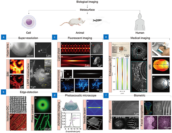
    Fig. 1. Representative metasurface-based bioimaging techniques for cell, animal, and human applications. (a, b) Metasurface-based (a) super-resolution and (b) edge-detection imaging for cell imaging applications. (a-i) Cross-section of hyperlens and (a-ii) neuronal super-resolution image using hyperlens. (a-iii) Diffraction-limited and (a-iv) super-resolution image of same cells using metasurface-assisted SIM, respectively. (a-v) LSPR imaging of live cell. (b-i) SEM image of edge-detection metasurface and (b-ii) i-DIC image of onion epidermal cell. (b-iii) PSF of spiral phase metasurface and (b-iv) edge-enhanced image of onion epidermal cells. (c, d) Metasurface-based (c) fluorescent and PAM for (d) animal imaging. (c i-iv) PSF of lattice light sheet microscope in (c-i) XY and (c-iii) XZ plane and in vivo fluorescent image of developing embryos obtained by (c-ii) wide field and (c-iv) light sheet microscope. (c-v) PSF of metasurface-based miniaturized two-photon microscope and (c-vi) fluorescent image of Thy1-YFP mouse brain at different depth. (d) Metasurface-based PSF engineering for PAM applications. (d-i, d-ii) Schematic and intensity profile of an achromatic metasurface for dual-channel PAM. (d-iii) Needle beam PSF and (d-iv) label-free histological PAM image. (e, f) Metasurface-based (e) medical imaging and (f) biometric devices. (e-i) Optical setup and (e-ii) PSF of metasurface-based endoscopic OCT system. (e-iii) Human lung images. (e iv-vi) Metasurface-assisted MRI images. (f-i) SEM image of metasurface and (f-ii) fingerprint image obtained. (f-iii) Illustration of metasurface-based point cloud generation and (f-iv, f-v) implementation of 3D facial recognition. Figure reproduced with permission from: (a) (i) ref.14, Springer Nature; (ii) ref.15 American Chemical Society; (iii, iv) ref.16, Springer Nature; (v) ref.17, American Chemical Society; (b) (i, ii) ref.18, American Chemical Society; (iii, iv) ref.19 Springer Nature; (c) (i-iii) ref.20, De Gruyter; (ii-iv) ref.21, De Gruyter; (v, vi) ref.22, American Chemical Society; (d) (i, ii) ref.23, Elsevier; (iii, iv) ref.24, Elsevier; (e) (i, iii) ref.25, Springer Nature; (iv, vi) ref.26, Springer Nature; (f) (i, ii) ref.27, American Chemical Society; (iii-v) ref.28, American Chemical Society.
    Working principles of phase modulation of metasurface. (a) Schematic of the generalized Snell's law of refraction. The phase gradient causes additional refraction of light. (b) SEM image of the circular meta-atoms of propagation phase metasurface. (c) SEM image of the rectangular meta-atoms on geometric phase metasurface. (d) Schematic illustrating the principle of combining propagation and geometric phases. (e) An illustration depicting the spectral dispersion of metasurface in terms of group delay. (f) For a metasurface with a 530 nm wavelength and a 49 μm focal length, the group delay and group dispersion delay profiles are shown. Based on the value of n, the design can be optimized for achromatic or chromatic performance. Figure reproduced with permission from: (a) ref.29, American Association for the Advancement of Science; (b) ref.32, American Chemical Society; (c) ref.33, American Chemical Society; (d) adapted with permission from ref. 34, copyrighted by the American Physical Society; (e, f) ref.12, Springer Nature.
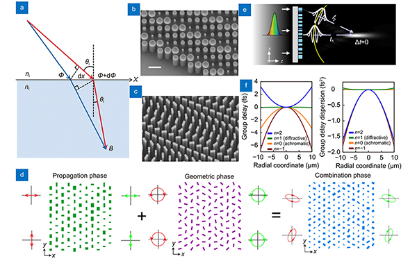
    Fig. 2. Working principles of phase modulation of metasurface. (a) Schematic of the generalized Snell's law of refraction. The phase gradient causes additional refraction of light. (b) SEM image of the circular meta-atoms of propagation phase metasurface. (c) SEM image of the rectangular meta-atoms on geometric phase metasurface. (d) Schematic illustrating the principle of combining propagation and geometric phases. (e) An illustration depicting the spectral dispersion of metasurface in terms of group delay. (f) For a metasurface with a 530 nm wavelength and a 49 μm focal length, the group delay and group dispersion delay profiles are shown. Based on the value of n, the design can be optimized for achromatic or chromatic performance. Figure reproduced with permission from: (a) ref.29, American Association for the Advancement of Science; (b) ref.32, American Chemical Society; (c) ref.33, American Chemical Society; (d) adapted with permission from ref. 34, copyrighted by the American Physical Society; (e, f) ref.12, Springer Nature.
    Representative metasurfaces consist of plasmonic and dielectric materials. (a) V-shaped plasmonic meta-atom. The V-antennas activate symmetric and antisymmetric modes depending on the incident light. The unit cells are periodically arranged to manipulate reflection and refraction of light. (b) SEM image of V-antennas showing the periodic arrangement of unit cells (left). A schematic illustrating the phase-delayed according to the generalized Snell's law (right). (c) Scattering, absorption, and SPP cross-sections of gap surface plasmon resonator (top). Distribution of electric field enhancement (bottom). (d) A dielectric scatterer with a typical size considerably smaller than the operating wavelength. Dielectric materials are chosen for their low-loss and high refractive index properties, which allow efficient phase and amplitude control. (e) Electric and magnetic field distribution of the silicon nanodisk metasurface (left). overlapped vector diagram of the electric field (right). Electric and magnetic dipole resonances can be simultaneously generated and overlapped to suppress the reflection of the metasurface. Through the careful design of the dielectric structure, it is possible to control the transmittance using resonance control. Figure reproduced with permission from: (a, b) ref.29, American Association for the Advancement of Science; (c) ref.82, Optics express; (d) ref.88, Optics express; (e) ref.89, John Wiley and Sons.
    Fig. 3. Representative metasurfaces consist of plasmonic and dielectric materials. (a) V-shaped plasmonic meta-atom. The V-antennas activate symmetric and antisymmetric modes depending on the incident light. The unit cells are periodically arranged to manipulate reflection and refraction of light. (b) SEM image of V-antennas showing the periodic arrangement of unit cells (left). A schematic illustrating the phase-delayed according to the generalized Snell's law (right). (c) Scattering, absorption, and SPP cross-sections of gap surface plasmon resonator (top). Distribution of electric field enhancement (bottom). (d) A dielectric scatterer with a typical size considerably smaller than the operating wavelength. Dielectric materials are chosen for their low-loss and high refractive index properties, which allow efficient phase and amplitude control. (e) Electric and magnetic field distribution of the silicon nanodisk metasurface (left). overlapped vector diagram of the electric field (right). Electric and magnetic dipole resonances can be simultaneously generated and overlapped to suppress the reflection of the metasurface. Through the careful design of the dielectric structure, it is possible to control the transmittance using resonance control. Figure reproduced with permission from: (a, b) ref.29, American Association for the Advancement of Science; (c) ref.82, Optics express; (d) ref.88, Optics express; (e) ref.89, John Wiley and Sons.
    Metasurfaces for super-resolution techniques for cell imaging application. (a, b) Optical setup of hyperlens-based (a) super-resolution imaging system, and (b) fluorescent image of cultured neuron. (c, d) Super-resolution FCS setup based on (c) STED, and (d) hyperlens. Scale bar: 200 nm. Figure reproduced with permission from: (a, b) ref.15, American Chemical Society; (c) ref.151, Springer Nature; (d) ref.152, Optical Society of America.
    Fig. 4. Metasurfaces for super-resolution techniques for cell imaging application. (a, b) Optical setup of hyperlens-based (a) super-resolution imaging system, and (b) fluorescent image of cultured neuron. (c, d) Super-resolution FCS setup based on (c) STED, and (d) hyperlens. Scale bar: 200 nm. Figure reproduced with permission from: (a, b) ref.15, American Chemical Society; (c) ref.151, Springer Nature; (d) ref.152, Optical Society of America.
    Edge-detection metasurfaces for cell imaging applications. (a) Images obtained at back focal plane of a standard metasurface and nanophotonic differentiator metasurface (top). Onion epidermis obtained with and without differentiator metasurface (bottom). Scale bar: 50 μm. (b) Human umbilical vein endothelial cells (top) and human bronchial epithelial cells (middle) taken by using brightfield, phase contrast, dark field, and edge-detection, respectively. Scale bar: 100 μm. (c) Amplitude and phase distributions calculated using the angular spectrum method (ASM) at the focal plane of a spiral metasurface. Scale bar: 250 nm. (d) Edge-detection metasurface compatible to incoherent light for general purpose imaging. (e) (i) Metasurface-assisted DIC image of the USAF 1951 resolution test chart under NA of 0.1 and 0.7, respectively. (ii) Images captured with wide-field and i-DIC microscope. Figure reproduced with permission from: (a) ref.182, Springer Nature; (b) ref.186, Oxford University Press; (c) ref.188, John Wiley and Sons; (d) ref.137, American Chemical Society; (e) ref.19, Springer Nature.
    Fig. 5. Edge-detection metasurfaces for cell imaging applications. (a) Images obtained at back focal plane of a standard metasurface and nanophotonic differentiator metasurface (top). Onion epidermis obtained with and without differentiator metasurface (bottom). Scale bar: 50 μm. (b) Human umbilical vein endothelial cells (top) and human bronchial epithelial cells (middle) taken by using brightfield, phase contrast, dark field, and edge-detection, respectively. Scale bar: 100 μm. (c) Amplitude and phase distributions calculated using the angular spectrum method (ASM) at the focal plane of a spiral metasurface. Scale bar: 250 nm. (d) Edge-detection metasurface compatible to incoherent light for general purpose imaging. (e) (i) Metasurface-assisted DIC image of the USAF 1951 resolution test chart under NA of 0.1 and 0.7, respectively. (ii) Images captured with wide-field and i-DIC microscope. Figure reproduced with permission from: (a) ref.182, Springer Nature; (b) ref.186, Oxford University Press; (c) ref.188, John Wiley and Sons; (d) ref.137, American Chemical Society; (e) ref.19, Springer Nature.
    Various tunable metasurfaces and representative working principles. (a) A liquid crystal cells combined electrically tunable edge-detection metasurface. Scale bar: 5 μm. (b) Stretchable zoom metasurface fabricated on elastic substrate. (c) A MEMS combined varifocal metasurface. The focal length can be controlled by adjusting the distance be-tween two lenses using MEMS. (d) A varifocal metasurface consists of thermally responsive material that deforms in its crystalline state under heating, thereby causing a change in refractive index. Figure reproduced with permission from: (a) ref.122, American Chemical Society; (b) ref.210, American Chemical Society; (c) ref.214, Springer Nature; (d) ref.112, Springer Nature.
    Fig. 6. Various tunable metasurfaces and representative working principles. (a) A liquid crystal cells combined electrically tunable edge-detection metasurface. Scale bar: 5 μm. (b) Stretchable zoom metasurface fabricated on elastic substrate. (c) A MEMS combined varifocal metasurface. The focal length can be controlled by adjusting the distance be-tween two lenses using MEMS. (d) A varifocal metasurface consists of thermally responsive material that deforms in its crystalline state under heating, thereby causing a change in refractive index. Figure reproduced with permission from: (a) ref.122, American Chemical Society; (b) ref.210, American Chemical Society; (c) ref.214, Springer Nature; (d) ref.112, Springer Nature.
    Various metasurfaces-derived fluorescent microscopies for animal imaging applications. (a) Geometry and structural parameters of unit cell consist of paired nanofins for achromatic metasurface. Scale bar: 500 nm. (b) PSF of achromatic metasurface at various wavelength. The focal plane (dotted line) coincides regardless of the wavelength. (c) Illustration of metasurface-based light sheet microscopy (top), along with a bright-field, light sheet fluorescent microscopy, and wide-field fluorescence image of C. elegans (bottom). (d) The complex phase profile of metasurface for lattice light-sheet and its PSF. (e) Miniaturized two-photon microscopy incorporating a metasurface. Figure reproduced with permission from: (a), (b) ref.12, Springer Nature; (c) ref.21, De Gruyter; (d) ref.20, De Gruyter; (e) ref.22, American Chemical Society.
    Fig. 7. Various metasurfaces-derived fluorescent microscopies for animal imaging applications. (a) Geometry and structural parameters of unit cell consist of paired nanofins for achromatic metasurface. Scale bar: 500 nm. (b) PSF of achromatic metasurface at various wavelength. The focal plane (dotted line) coincides regardless of the wavelength. (c) Illustration of metasurface-based light sheet microscopy (top), along with a bright-field, light sheet fluorescent microscopy, and wide-field fluorescence image of C. elegans (bottom). (d) The complex phase profile of metasurface for lattice light-sheet and its PSF. (e) Miniaturized two-photon microscopy incorporating a metasurface. Figure reproduced with permission from: (a), (b) ref.12, Springer Nature; (c) ref.21, De Gruyter; (d) ref.20, De Gruyter; (e) ref.22, American Chemical Society.
    Metasurface-based PSF engineering for photoacoustic microscopy applications. (a) A comparison of PSF between a conventional objective lens with a NA of 0.13 and a metasurface designed for extended depth of focus at UV wavelength. The objective lens has a depth of focus of 28 µm, whereas the metasurface has a depth of focus of 216 µm. (b) Optical setup for dual-channel PAM using a UV-Visible metasurface (top). PAM imaging simulation and resulting intensity profiles of phantom at UV and visible light (bottom). Figure reproduced with permission from: (a) ref.244, Optical Society of America; (b) ref.23, Elsevier.
    Fig. 8. Metasurface-based PSF engineering for photoacoustic microscopy applications. (a) A comparison of PSF between a conventional objective lens with a NA of 0.13 and a metasurface designed for extended depth of focus at UV wavelength. The objective lens has a depth of focus of 28 µm, whereas the metasurface has a depth of focus of 216 µm. (b) Optical setup for dual-channel PAM using a UV-Visible metasurface (top). PAM imaging simulation and resulting intensity profiles of phantom at UV and visible light (bottom). Figure reproduced with permission from: (a) ref.244, Optical Society of America; (b) ref.23, Elsevier.
    Biomedical applications of metasurfaces. (a) Schematic (top), and distal end of the nano-optic endoscope using ultra-thin metasurface. (b) Comparison of PSF at a wavelength of 1310 nm for an OCT catheter based on GRIN, ball, and metasurface, respectively. The metasurface-based OCT catheter shows the clearest PSF. (c) The image of fruit flesh of grape (left) and swine airway (right) obtained from the metasurface-based nano-optic endoscope. Scale bar: 500 μm. (d) Full color video rate imaging of caterpillar on a strawberry leaf taken from meta-optical fiber endoscope. Scale bar: 500 μm. (e) Illustration of MRI scanning with metasurface made of a high permittivity dielectric pad and metal stripes. (f) Schematic and simulation results of metasurface assisted MRI scanning. Homogeneous magnetic field enhancement is observed. Figure reproduced with permission from: (a–c) ref.25, Springer Nature; (d) ref.257, Springer Nature; (e) ref.26, Springer Nature; (f) ref.263, Springer Nature.
    Fig. 9. Biomedical applications of metasurfaces. (a) Schematic (top), and distal end of the nano-optic endoscope using ultra-thin metasurface. (b) Comparison of PSF at a wavelength of 1310 nm for an OCT catheter based on GRIN, ball, and metasurface, respectively. The metasurface-based OCT catheter shows the clearest PSF. (c) The image of fruit flesh of grape (left) and swine airway (right) obtained from the metasurface-based nano-optic endoscope. Scale bar: 500 μm. (d) Full color video rate imaging of caterpillar on a strawberry leaf taken from meta-optical fiber endoscope. Scale bar: 500 μm. (e) Illustration of MRI scanning with metasurface made of a high permittivity dielectric pad and metal stripes. (f) Schematic and simulation results of metasurface assisted MRI scanning. Homogeneous magnetic field enhancement is observed. Figure reproduced with permission from: (a–c) ref.25, Springer Nature; (d) ref.257, Springer Nature; (e) ref.26, Springer Nature; (f) ref.263, Springer Nature.
    Representative metasurface integrated devices for biometric applications. (a) Implementation of 3D facial depth sensing using a point cloud generating metasurface. (b) Illustration of a metasurface-based dot projector combined with PCSEL, which is 233 times smaller than a commercial DOE-based dot projector. (c) Schematic of metasurface-based device for fingerprint recognition (left) and fingerprint image obtained by the device. (d) Fingerprint image obtained using a metasurface array imaging device. The array structure enables the acquisi-tion of clearer and wider fingerprint images. Figure reproduced with permission from: (a) ref.49, Springer Nature; (b) ref.28, American Chemical Society; (c) ref.27, American Chemical Society; (d) ref.283, De Gruyter.
    Fig. 10. Representative metasurface integrated devices for biometric applications. (a) Implementation of 3D facial depth sensing using a point cloud generating metasurface. (b) Illustration of a metasurface-based dot projector combined with PCSEL, which is 233 times smaller than a commercial DOE-based dot projector. (c) Schematic of metasurface-based device for fingerprint recognition (left) and fingerprint image obtained by the device. (d) Fingerprint image obtained using a metasurface array imaging device. The array structure enables the acquisi-tion of clearer and wider fingerprint images. Figure reproduced with permission from: (a) ref.49, Springer Nature; (b) ref.28, American Chemical Society; (c) ref.27, American Chemical Society; (d) ref.283, De Gruyter.
    Yongjae Jo, Hyemi Park, Hyeyoung Yoon, Inki Kim. Advanced biological imaging techniques based on metasurfaces[J]. Opto-Electronic Advances, 2024, 7(12): 240122
    Download Citation